Netgear FVS318G FVS318G User Manual - Page 144
Create New SNMP Configuration Entry, IP Address, Subnet Mask, Community, Configuration
 |
UPC - 606449064827
View all Netgear FVS318G manuals
Add to My Manuals
Save this manual to your list of manuals |
Page 144 highlights
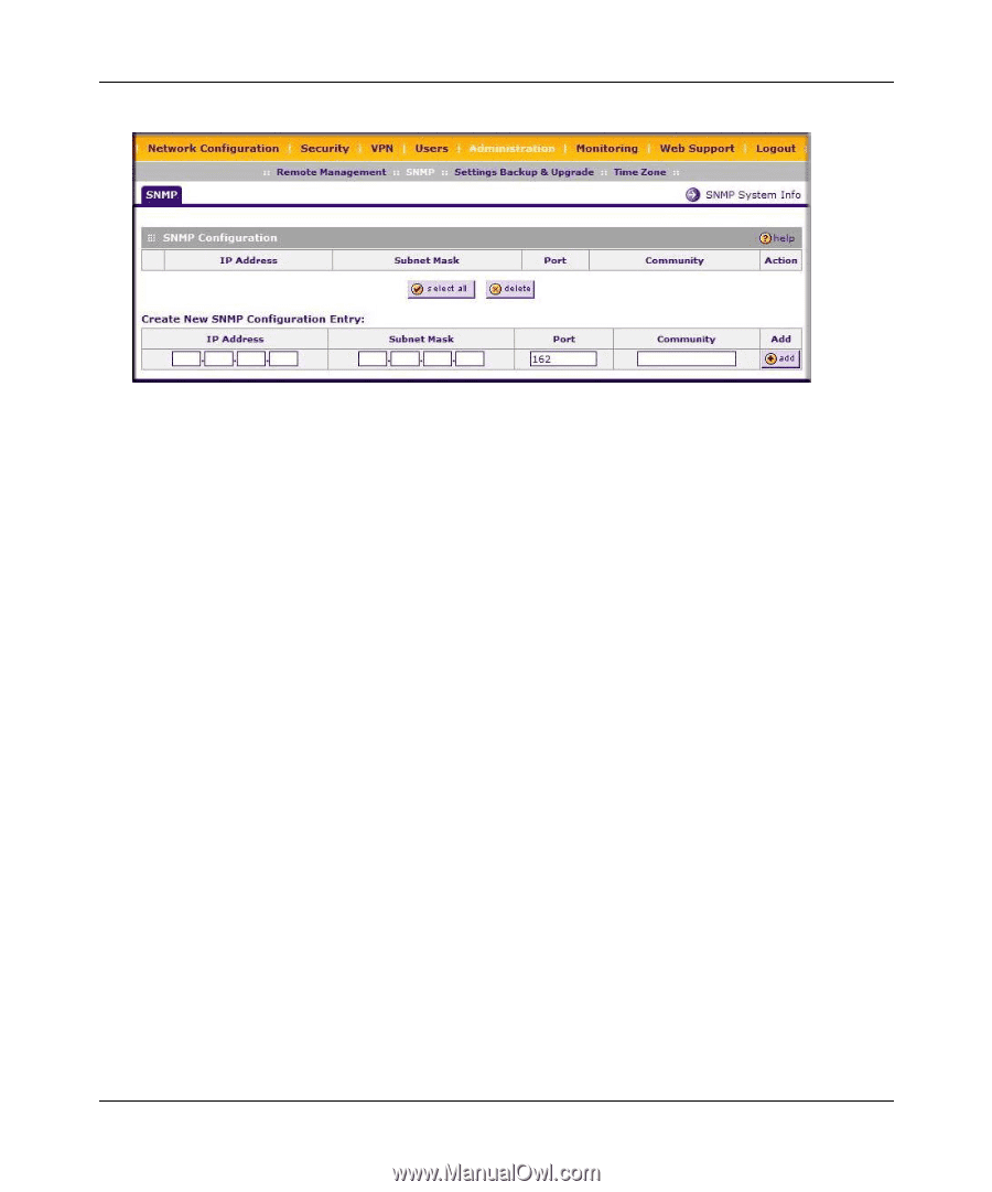
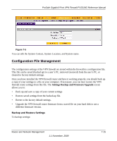
ProSafe Gigabit 8 Port VPN Firewall FVS318G Reference Manual . Figure 7-4 2. Configure the following fields in the Create New SNMP Configuration Entry section: a. Enter the IP Address of the SNMP manager in the IP Address field and the Subnet Mask in the Subnet Mask field. - To allow only the host address to access the VPN firewall router and receive traps, enter an IP Address of, for example, 192.168.1.101 with a Subnet Mask of 255.255.255.255. - To allow a subnet access to the VPN firewall router through SNMP, enter an IP address of, for example,192.168.1.101 with a Subnet Mask of 255.255.255.0. The traps will still be received on 192.168.1.101, but the entire subnet will have access through the community string. - To make the VPN firewall router globally accessible using the community string, but still receive traps on the host, enter 0.0.0.0 as the Subnet Mask and an IP Address for where the traps will be received. b. Enter the trap port number of the configuration in the Port field. The default is 162. c. Enter the trap community string of the configuration in the Community field. 3. Click Add to create the new configuration. The entry is displayed in the SNMP Configuration table. The SNMP System Info option arrow at the top of the tab opens the SNMP SysConfiguration menu that displays the SNMP System contact information available to the SNMP manager: 7-14 1.1 November, 2009 Router and Network Management
-
 1
1 -
2
-
3
-
4
-
5
-
6
-
7
-
8
-
9
-
10
-
11
-
12
-
13
-
14
-
15
-
16
-
17
-
18
-
19
-
20
-
21
-
22
-
23
-
24
-
25
-
26
-
27
-
28
-
29
-
30
-
31
-
32
-
33
-
34
-
35
-
36
-
37
-
38
-
39
-
40
-
41
-
42
-
43
-
44
-
45
-
46
-
47
-
48
-
49
-
50
-
51
-
52
-
53
-
54
-
55
-
56
-
57
-
58
-
59
-
60
-
61
-
62
-
63
-
64
-
65
-
66
-
67
-
68
-
69
-
70
-
71
-
72
-
73
-
74
-
75
-
76
-
77
-
78
-
79
-
80
-
81
-
82
-
83
-
84
-
85
-
86
-
87
-
88
-
89
-
90
-
91
-
92
-
93
-
94
-
95
-
96
-
97
-
98
-
99
-
100
-
101
-
102
-
103
-
104
-
105
-
106
-
107
-
108
-
109
-
110
-
111
-
112
-
113
-
114
-
115
-
116
-
117
-
118
-
119
-
120
-
121
-
122
-
123
-
124
-
125
-
126
-
127
-
128
-
129
-
130
-
131
-
132
-
133
-
134
-
135
-
136
-
137
-
138
-
 139
139 -
 140
140 -
 141
141 -
 142
142 -
 143
143 -
 144
144 -
 145
145 -
 146
146 -
 147
147 -
 148
148 -
 149
149 -
150
-
151
-
152
-
153
-
154
-
155
-
156
-
157
-
158
-
159
-
160
-
161
-
162
-
163
-
164
-
165
-
166
-
167
-
168
-
169
-
170
-
171
-
172
-
173
-
174
-
175
-
176
-
177
-
178
-
179
-
180
 |
 |