Netgear FVS318G FVS318G User Manual - Page 67
VPN firewall FVS318G, LAN IP address 192.168.1.1
 |
UPC - 606449064827
View all Netgear FVS318G manuals
Add to My Manuals
Save this manual to your list of manuals |
Page 67 highlights
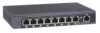
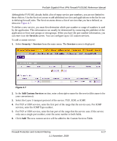
ProSafe Gigabit 8 Port VPN Firewall FVS318G Reference Manual In the example shown in Figure 4-6, we have configured multi-NAT to support multiple public IP addresses on one WAN interface. The inbound rule instructs the VPN firewall to host an additional public IP address (10.1.0.5) and to associate this address with the Web server on the LAN (at 192.168.1.2). We also instruct the VPN firewall to translate the incoming HTTP port number (port 80) to a different port number (port 8080). Figure 4-6 The following addressing scheme is used in this example: • VPN firewall FVS318G - WAN1 primary public IP address: 10.1.0.1 - WAN1 additional public IP address: 10.1.0.5 - LAN IP address 192.168.1.1 • Web server PC on the VPN firewall's LAN - LAN IP address: 192.168.1.11 - Port number for Web service: 8080 To test the connection from a PC on the WAN side, type http://10.1.0.5. The home page of the Web server should appear. Firewall Protection and Content Filtering 1.1 November, 2009 4-15
-
 1
1 -
2
-
3
-
4
-
5
-
6
-
7
-
8
-
9
-
10
-
11
-
12
-
13
-
14
-
15
-
16
-
17
-
18
-
19
-
20
-
21
-
22
-
23
-
24
-
25
-
26
-
27
-
28
-
29
-
30
-
31
-
32
-
33
-
34
-
35
-
36
-
37
-
38
-
39
-
40
-
41
-
42
-
43
-
44
-
45
-
46
-
47
-
48
-
49
-
50
-
51
-
52
-
53
-
54
-
55
-
56
-
57
-
58
-
59
-
60
-
61
-
 62
62 -
 63
63 -
 64
64 -
 65
65 -
 66
66 -
 67
67 -
 68
68 -
 69
69 -
 70
70 -
 71
71 -
 72
72 -
73
-
74
-
75
-
76
-
77
-
78
-
79
-
80
-
81
-
82
-
83
-
84
-
85
-
86
-
87
-
88
-
89
-
90
-
91
-
92
-
93
-
94
-
95
-
96
-
97
-
98
-
99
-
100
-
101
-
102
-
103
-
104
-
105
-
106
-
107
-
108
-
109
-
110
-
111
-
112
-
113
-
114
-
115
-
116
-
117
-
118
-
119
-
120
-
121
-
122
-
123
-
124
-
125
-
126
-
127
-
128
-
129
-
130
-
131
-
132
-
133
-
134
-
135
-
136
-
137
-
138
-
139
-
140
-
141
-
142
-
143
-
144
-
145
-
146
-
147
-
148
-
149
-
150
-
151
-
152
-
153
-
154
-
155
-
156
-
157
-
158
-
159
-
160
-
161
-
162
-
163
-
164
-
165
-
166
-
167
-
168
-
169
-
170
-
171
-
172
-
173
-
174
-
175
-
176
-
177
-
178
-
179
-
180
 |
 |