Sony PDWHD1500 User Manual (PDW-HD1500 Operation Manual for Firmware Version 1 - Page 114
thru through, Item number
 |
View all Sony PDWHD1500 manuals
Add to My Manuals
Save this manual to your list of manuals |
Page 114 highlights
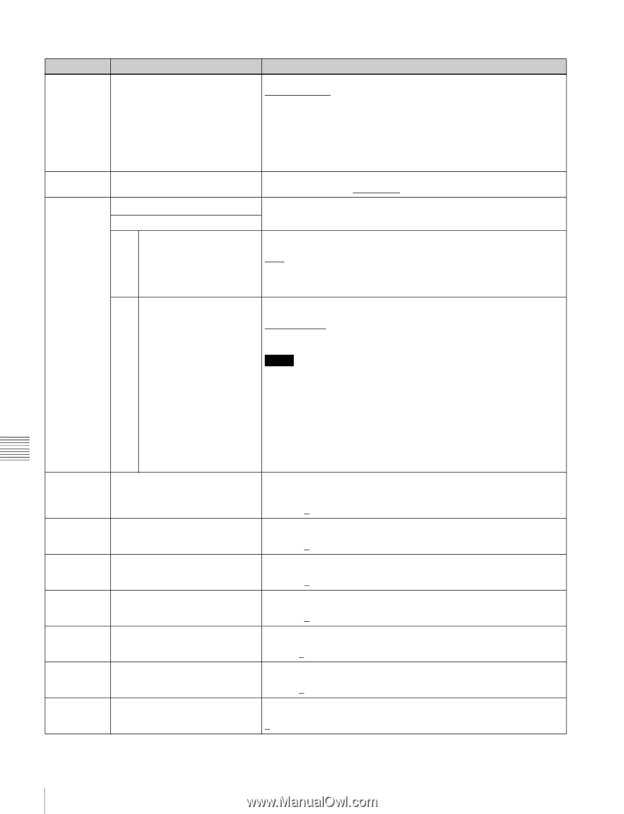
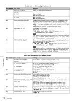
Menu items in the 700s, relating to video control Item number Item name 726 H BLANKING WIDTH 728 OUTPUT SCH PHASE 731 WIDE MODE Sub-Item 1 INPUT a) 2 OUTPUT Settings Select the horizontal blanking width of the output analog video signal. narow (narrow): Digital blanking (narrow) wide: Analog blanking (wide) When "wide" is selected, the horizontal blanking width complies with SMPTE170M, and normally the blanking is widened and the image becomes narrower. It is recommended to select "narow" at the editing stage, then later, for broadcast transmission to select "wide", to output a signal conforming to the standard. Note, however, that "narow" has to be always selected for SDI signals. Set the subcarrier H phase. -512 (-512 (DEC))... 0 (0 (DEC))... 511 (511 (DEC)) Specify whether to record and play back with the addition of wide picture information. Select whether to save wide picture information to the disc when recording. auto: Automatically save wide picture information when it is detected in the selected input video signal. on: Always save wide picture information. off: Never save wide picture information. Select whether to add wide picture information to the signal output when down-converter output is set to squeeze mode. thru (through): Do not add. auto: Add. 740 MASTER LEVEL (HD) 741 Y LEVEL (HD) 742 PB LEVEL (HD) 743 PR LEVEL (HD) 745 SETUP LEVEL (HD) 746 SYNC PHASE (HD) 747 FINE (HD) Notes • To add wide picture information to the output signal, another setting is required in addition to this item. In setup menu item 703, set line 16 (59.94i/59.94P/29.97P mode (J)), line 20 (59.94i/59.94P/29.97P mode (UC)), or line 23(50i/50P/25P mode) to "thru". • In 59.94i/59.94P/29.97P mode (J), output of wide picture information is given priority if the VITC insertion line is set to line 16 in setup menu item 601 or 602. • In 59.94i/59.94P/29.97P mode (UC), output of wide picture information is given priority if the VITC insertion line is set to line 20 in setup menu item 601 or 602. Adjust the high-definition video signal output from the HDSDI OUTPUT 1, 2 (SUPER) connectors. This adjusts the Y, PB, and PR levels simultaneously. -2048 to 0 to 846 Adjust the Y level of the high-definition video signal output from the HDSDI OUTPUT 1, 2 (SUPER) connectors. -2048 to 0 to 846 Adjust the PB level of the high-definition video signal output from the HDSDI OUTPUT 1, 2 (SUPER) connectors. -2048 to 0 to 846 Adjust the PR level of the high-definition video signal output from the HDSDI OUTPUT 1, 2 (SUPER) connectors. -2048 to 0 to 846 Adjust the setup level of the high-definition video signal output from the HDSDI OUTPUT 1, 2 (SUPER) connectors. -272 to 0 to 272 Control the H sync phase of the high-definition video signal output from the HDSDI OUTPUT 1, 2 (SUPER) connectors. -128 to 0 to 127 Fine control the H sync phase of the high-definition video signal output from the HDSDI OUTPUT 1, 2 (SUPER) connectors. 0 to 1023 a) When the separately sold PDBK-S1500 option is installed. Chapter 7 Menus 114 Setup Menu
-
 1
1 -
2
-
3
-
4
-
5
-
6
-
7
-
8
-
9
-
10
-
11
-
12
-
13
-
14
-
15
-
16
-
17
-
18
-
19
-
20
-
21
-
22
-
23
-
24
-
25
-
26
-
27
-
28
-
29
-
30
-
31
-
32
-
33
-
34
-
35
-
36
-
37
-
38
-
39
-
40
-
41
-
42
-
43
-
44
-
45
-
46
-
47
-
48
-
49
-
50
-
51
-
52
-
53
-
54
-
55
-
56
-
57
-
58
-
59
-
60
-
61
-
62
-
63
-
64
-
65
-
66
-
67
-
68
-
69
-
70
-
71
-
72
-
73
-
74
-
75
-
76
-
77
-
78
-
79
-
80
-
81
-
82
-
83
-
84
-
85
-
86
-
87
-
88
-
89
-
90
-
91
-
92
-
93
-
94
-
95
-
96
-
97
-
98
-
99
-
100
-
101
-
102
-
103
-
104
-
105
-
106
-
107
-
108
-
 109
109 -
 110
110 -
 111
111 -
 112
112 -
 113
113 -
 114
114 -
 115
115 -
 116
116 -
 117
117 -
 118
118 -
 119
119 -
120
-
121
-
122
-
123
-
124
-
125
-
126
-
127
-
128
-
129
-
130
-
131
-
132
-
133
-
134
-
135
-
136
-
137
-
138
-
139
-
140
-
141
-
142
-
143
-
144
-
145
-
146
-
147
-
148
-
149
-
150
-
151
-
152
-
153
-
154
-
155
-
156
-
157
-
158
 |
 |