Sony PDWHD1500 User Manual (PDW-HD1500 Operation Manual for Firmware Version 1 - Page 43
P1 Video P2 Audio Ch2, Ch3, Ch4, Ch5, Ch6, Ch7
 |
View all Sony PDWHD1500 manuals
Add to My Manuals
Save this manual to your list of manuals |
Page 43 highlights
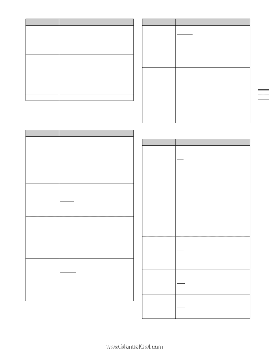
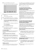
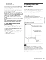
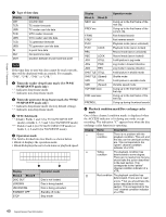
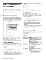
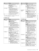
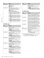
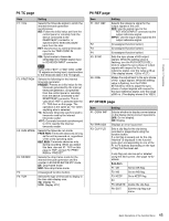
Chapter 3 Preparations Item F4: CNTR SEL F5: TCG SET F6: Setting Selects the type of time data to display in the time data display area. TC: Timecode COUNTER: Elapsed recording or playback time UB: User bits • When CNTR SEL is set to "TC" , displays a screen where you can set the initial value of the timecode generated by the internal timecode generator a) (see page 37). • When CNTR SEL is set to "UB" , displays a screen where you can set timecode user bits a) (see page 38). (Unassigned function button) a) This is displayed only when TCG on page P5 TC of the function menu is set to "INT", and PRST/RGN is set to "PRESET". P1 VIDEO page Item F1: V INPUT F2: VID. PROC F3: VIDEO F4: CHROMA Setting Selects the video input signal. HDSDI: HDSDI signal SDSDI: SDSDI signal i.LINK: i.LINK signal (when the separately sold PDBK-201 option board is installed) SG: Test signal from internal signal generator (Normally this item is not displayed. It appears when you hold the button down for 3 seconds.) Selects the method used to control the internal video signal processor and make related settings. LOCAL: Use the function menu to change settings. MENU: Use the setup menu to change settings. Sets the output level for HD/SD video signals (range -∞ to +3 dB). PRESET: Set the video signal output level to a preset value, regardless of manual setting. Manual setting: While the setting value is flashing, turn the PUSH SET(S.SEL) knob to adjust the video signal output level. Sets the output level for HD/SD chroma signals (range -∞ to +3 dB). PRESET: Set the chroma signal output level to a preset value, regardless of manual setting. Manual setting: While the setting value is flashing, turn the PUSH SET(S.SEL) knob to adjust the chroma SETUP signal output level. Item F5: HUE/CHRM PHS F6: SETUP/ BLACK Setting Sets the hue (chroma phase). PRESET: Set the hue (chroma phase) to a preset value, regardless of manual setting. Manual setting: While the setting value is flashing, turn the PUSH SET(S.SEL) knob to adjust the hue (chroma phase) over the range ±30°. Sets the HD/SD output black setup level or black level. PRESET: Set the level to the preset value, regardless of the manual setting. Manual setting: While the setting value is flashing, turn the PUSH SET(S.SEL) knob to set the black setup level (in 59.94i/59.94P/29.97P mode) over the range ±30 IRE or the black level (in 50i/50P/25P mode) over the range ±210 mV. P2 AUDIO page Item F1: A1 INPUT F2: A2 INPUT F3: MONITR L F4: MONITR R Setting Selects the audio input signal to assign to audio channel 1. SDI: Audio signal embedded into SDI signal ANALOG1: Analog 1 audio signal AES/EBU1: Signal input to the DIGITAL AUDIO(AES/EBU) IN 1/2 connectors SG: Test signal from internal signal generator (Normally this item is not displayed. It appears when you hold the button down for 3 seconds. The test signal is assigned to audio channels 1 to 8 simultaneously.) Press one of the function buttons corresponding to A1 INPUT to A8 INPUT again to stop output of the test signal. i.LINK: i.LINK signal (when the separately sold PDBK-201 option board is installed) Selects the audio input signal to assign to audio channel 2. SDI: Audio signal embedded into SDI signal ANALOG2: Analog 2 audio signal AES/EBU2: Signal input to the DIGITAL AUDIO(AES/EBU) IN 1/2 connectors Selects the channel to monitor as the left monitor channel. CH1, CH2, CH3, CH4, CH5, CH6, CH7, CH8 CH1/2, CH3/4, CH5/6, CH7/8 (MIX) Selects the channel to monitor as the right monitor channel. CH1, CH2, CH3, CH4, CH5, CH6, CH7, CH8 CH1/2, CH3/4, CH5/6, CH7/8 (MIX) 43 Basic Operations of the Function Menu
-
 1
1 -
2
-
3
-
4
-
5
-
6
-
7
-
8
-
9
-
10
-
11
-
12
-
13
-
14
-
15
-
16
-
17
-
18
-
19
-
20
-
21
-
22
-
23
-
24
-
25
-
26
-
27
-
28
-
29
-
30
-
31
-
32
-
33
-
34
-
35
-
36
-
37
-
 38
38 -
 39
39 -
 40
40 -
 41
41 -
 42
42 -
 43
43 -
 44
44 -
 45
45 -
 46
46 -
 47
47 -
 48
48 -
49
-
50
-
51
-
52
-
53
-
54
-
55
-
56
-
57
-
58
-
59
-
60
-
61
-
62
-
63
-
64
-
65
-
66
-
67
-
68
-
69
-
70
-
71
-
72
-
73
-
74
-
75
-
76
-
77
-
78
-
79
-
80
-
81
-
82
-
83
-
84
-
85
-
86
-
87
-
88
-
89
-
90
-
91
-
92
-
93
-
94
-
95
-
96
-
97
-
98
-
99
-
100
-
101
-
102
-
103
-
104
-
105
-
106
-
107
-
108
-
109
-
110
-
111
-
112
-
113
-
114
-
115
-
116
-
117
-
118
-
119
-
120
-
121
-
122
-
123
-
124
-
125
-
126
-
127
-
128
-
129
-
130
-
131
-
132
-
133
-
134
-
135
-
136
-
137
-
138
-
139
-
140
-
141
-
142
-
143
-
144
-
145
-
146
-
147
-
148
-
149
-
150
-
151
-
152
-
153
-
154
-
155
-
156
-
157
-
158
 |
 |