Sony PDWHD1500 User Manual (PDW-HD1500 Operation Manual for Firmware Version 1 - Page 44
P3 Audio Right, Left4, Setting, Analog1, Aes/ebu3
 |
View all Sony PDWHD1500 manuals
Add to My Manuals
Save this manual to your list of manuals |
Page 44 highlights
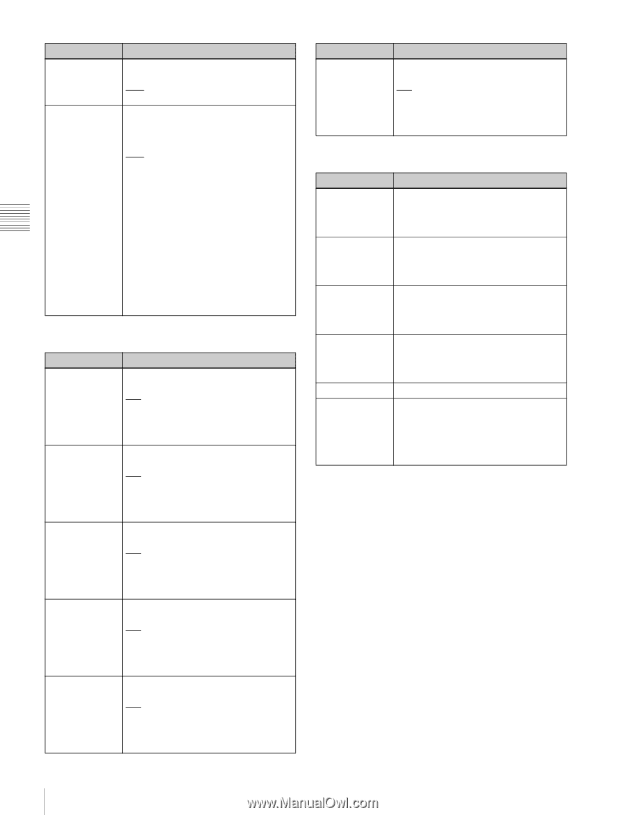
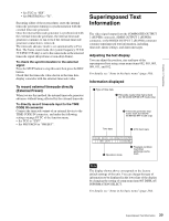
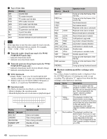
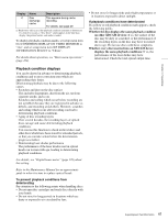
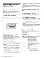
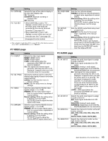
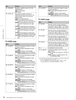
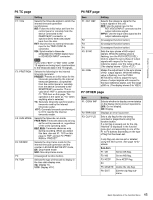
Chapter 3 Preparations Item F5: SPEAKER F6: LEVEL MT Setting Enables or disables output from this unit's speaker. OFF: Do not output ON: Output Specifies the position at which to superimpose audio level meters in the video monitor screen (in full-screen display mode). OFF: Do not superimpose. LEFT: Superimpose the audio level meters of 2 channels on the left side. RIGHT: Superimpose the audio level meters of 2 channels on the right side. LEFT(4): Superimpose the audio level meters of 4 channels on the left side. RIGHT(4): Superimpose the audio level meters of 4 channels on the right side. LEFT(8): Superimpose the audio level meters of 8 channels on the left side. RIGHT(8): Superimpose the audio level meters of 8 channels on the right side. P3 AUDIO page Item F1: A3 INPUT F2: A4 INPUT F3: A5 INPUT F4: A6 INPUT F5: A7 INPUT Setting Selects the audio input signal to assign to audio channel 3. SDI: Audio signal embedded into SDI signal ANALOG1: Analog 1 audio signal AES/EBU3: Signal input to the DIGITAL AUDIO(AES/EBU) IN 3/4 connectors Selects the audio input signal to assign to audio channel 4. SDI: Audio signal embedded into SDI signal ANALOG2: Analog 2 audio signal AES/EBU4: Signal input to the DIGITAL AUDIO(AES/EBU) IN 3/4 connectors Selects the audio input signal to assign to audio channel 5. SDI: Audio signal embedded into SDI signal ANALOG1: Analog 1 audio signal AES/EBU1: Signal input to the DIGITAL AUDIO(AES/EBU) IN 1/2 connectors Selects the audio input signal to assign to audio channel 6. SDI: Audio signal embedded into SDI signal ANALOG2: Analog 2 audio signal AES/EBU2: Signal input to the DIGITAL AUDIO(AES/EBU) IN 1/2 connectors Selects the audio input signal to assign to audio channel 7. SDI: Audio signal embedded into SDI signal ANALOG1: Analog 1 audio signal AES/EBU3: Signal input to the DIGITAL AUDIO(AES/EBU) IN 3/4 connectors Item F6: A8 INPUT Setting Selects the audio input signal to assign to audio channel 8. SDI: Audio signal embedded into SDI signal ANALOG2: Analog 2 audio signal AES/EBU4: Signal input to the DIGITAL AUDIO(AES/EBU) IN 3/4 connectors P4 AUDIO page Item F1: A5 VOL F2: A6 VOL F3: A7 VOL F4: A8 VOL F5: --F6: AU METER Setting Sets the volume of audio channel 5. a) The volume can be adjusted within the range from -200 to +200 (-∞ to +12 dB) by turning the PUSH SET(S.SEL) knob. Sets the volume of audio channel 6. a) The volume can be adjusted within the range from -200 to +200 (-∞ to +12 dB) by turning the PUSH SET(S.SEL) knob. Sets the volume of audio channel 7. a) The volume can be adjusted within the range from -200 to +200 (-∞ to +12 dB) by turning the PUSH SET(S.SEL) knob. Sets the volume of audio channel 8. a) The volume can be adjusted within the range from -200 to +200 (-∞ to +12 dB) by turning the PUSH SET(S.SEL) knob. (Unassigned function button) Selects the display mode of the audio level meters. FULL: Display the range from -60 dB to 0 dB. FINE: Display a magnified section with 0.25 dB step marks. a) To enable this setting, the following settings are also required, in the same way as for volume operations for channels 1 to 4. - Set the VARIABLE switch of the front panel to "REC" or "PB". - Set setup menu item 131 AUDIO VOLUME to "EACH". 44 Basic Operations of the Function Menu
-
 1
1 -
2
-
3
-
4
-
5
-
6
-
7
-
8
-
9
-
10
-
11
-
12
-
13
-
14
-
15
-
16
-
17
-
18
-
19
-
20
-
21
-
22
-
23
-
24
-
25
-
26
-
27
-
28
-
29
-
30
-
31
-
32
-
33
-
34
-
35
-
36
-
37
-
38
-
 39
39 -
 40
40 -
 41
41 -
 42
42 -
 43
43 -
 44
44 -
 45
45 -
 46
46 -
 47
47 -
 48
48 -
 49
49 -
50
-
51
-
52
-
53
-
54
-
55
-
56
-
57
-
58
-
59
-
60
-
61
-
62
-
63
-
64
-
65
-
66
-
67
-
68
-
69
-
70
-
71
-
72
-
73
-
74
-
75
-
76
-
77
-
78
-
79
-
80
-
81
-
82
-
83
-
84
-
85
-
86
-
87
-
88
-
89
-
90
-
91
-
92
-
93
-
94
-
95
-
96
-
97
-
98
-
99
-
100
-
101
-
102
-
103
-
104
-
105
-
106
-
107
-
108
-
109
-
110
-
111
-
112
-
113
-
114
-
115
-
116
-
117
-
118
-
119
-
120
-
121
-
122
-
123
-
124
-
125
-
126
-
127
-
128
-
129
-
130
-
131
-
132
-
133
-
134
-
135
-
136
-
137
-
138
-
139
-
140
-
141
-
142
-
143
-
144
-
145
-
146
-
147
-
148
-
149
-
150
-
151
-
152
-
153
-
154
-
155
-
156
-
157
-
158
 |
 |