Sony PDWHD1500 User Manual (PDW-HD1500 Operation Manual for Firmware Version 1 - Page 19
Clip information, Meter display mode: FULL
 |
View all Sony PDWHD1500 manuals
Add to My Manuals
Save this manual to your list of manuals |
Page 19 highlights
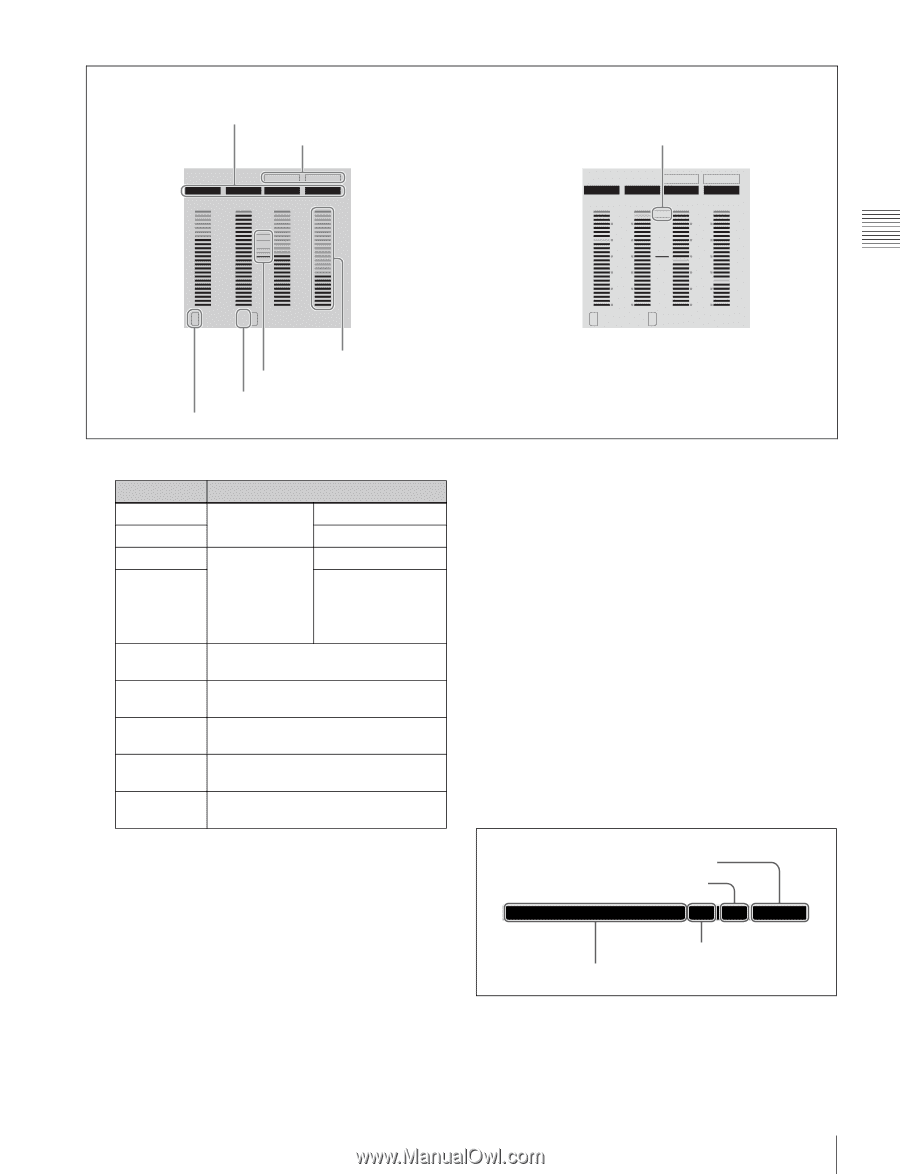
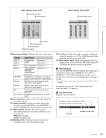
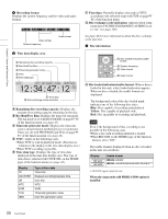
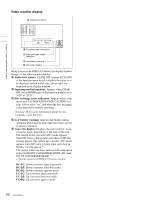
Chapter 2 Names and Functions of Parts Meter display mode: FULL A Input signal display B Data indication Meter display mode: FINE G Meter display mode DATA DATA AES/EBU AES/EBU HD-SDI HD-SDI 0 -10 -20 -30 -40 -60 L1 2R 0 -10 -20 -30 -40 -60 34 F Level bar E Reference level D Audio channel C Monitor channel DATA DATA AES/EBU AES/EBU HD-SDI HD-SDI FINE 2 2 1 1 0 0 -1 -1 -2 -2 L1 2 R 3 4 A Input signal display: Displays the audio input signal. . Display Input signal ANA-1 ANA-2 Analog audio signal Channel 1, 3 Channel 2, 4 MIC-1 MIC-2 Input signal from Channel 1, 3 the microphone connected to Channel 2, 4 ANALOG AUDIO INPUT connector AES/EBU AES/EBU format digital audio signal (flashes when there is no input signal) HD-SDI HDSDI audio signal (flashes when there is no input signal) SD-SDI SDSDI audio signal (flashes when there is no input signal) SG Test signal from the internal signal generator No indication Undefined audio signal, or no audio input B Data indication: Appears when the input signals are non-audio signals. C Monitor channel: Displays the audio monitoring channels set with MONITR L and MONITR R on page P2 AUDIO of the function menu (see page 43). D Audio channel: Displays the audio channels. Also indicates preset or variable mode by its color (see page 14). White: Preset mode Green: Variable mode E Reference level: Displays the reference level for recording as set in the maintenance menu. F Level bars: Display the audio recording or playback levels of channels 1 to 8. The OVER indicators light when the audio level exceeds 0 dB. G Meter display mode: Displays the audio level meter display mode selected with AU METER on page P4 AUDIO of the function menu (see page 44). b Function menu Use the PAGE/HOME button to display this menu, and to switch between the pages (HOME, P1 to P7, (P8) 1), (HOME2) 1) ) of the menu. Each page has three to six setting items. Press the corresponding button to change a setting. 1) If a menu item is assigned using maintenance menu item M38: F-KEY CONFIG For details, see page 42 "Basic Operations of the Function Menu" in Chapter 3. c Clip information Displays clip information. All remaining clips or clip list playback time Total number of clips recorded on disc PDW-HD1500 001/001 000:00 Clip name Number of current clip 19 Front Panel
-
 1
1 -
2
-
3
-
4
-
5
-
6
-
7
-
8
-
9
-
10
-
11
-
12
-
13
-
 14
14 -
 15
15 -
 16
16 -
 17
17 -
 18
18 -
 19
19 -
 20
20 -
 21
21 -
 22
22 -
 23
23 -
 24
24 -
25
-
26
-
27
-
28
-
29
-
30
-
31
-
32
-
33
-
34
-
35
-
36
-
37
-
38
-
39
-
40
-
41
-
42
-
43
-
44
-
45
-
46
-
47
-
48
-
49
-
50
-
51
-
52
-
53
-
54
-
55
-
56
-
57
-
58
-
59
-
60
-
61
-
62
-
63
-
64
-
65
-
66
-
67
-
68
-
69
-
70
-
71
-
72
-
73
-
74
-
75
-
76
-
77
-
78
-
79
-
80
-
81
-
82
-
83
-
84
-
85
-
86
-
87
-
88
-
89
-
90
-
91
-
92
-
93
-
94
-
95
-
96
-
97
-
98
-
99
-
100
-
101
-
102
-
103
-
104
-
105
-
106
-
107
-
108
-
109
-
110
-
111
-
112
-
113
-
114
-
115
-
116
-
117
-
118
-
119
-
120
-
121
-
122
-
123
-
124
-
125
-
126
-
127
-
128
-
129
-
130
-
131
-
132
-
133
-
134
-
135
-
136
-
137
-
138
-
139
-
140
-
141
-
142
-
143
-
144
-
145
-
146
-
147
-
148
-
149
-
150
-
151
-
152
-
153
-
154
-
155
-
156
-
157
-
158
 |
 |