Epson EPL-7000 User Manual - Page 264

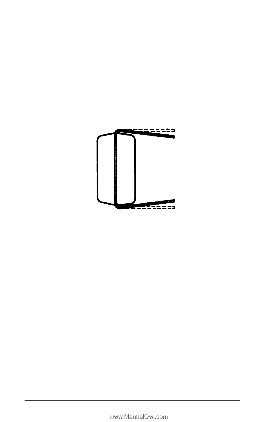
should point inward at slightly less than a 90° angle as shown, If any of the pins are bent

Page 264 highlights

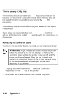
The Memory Chip Set If all three sectors are empty, install the chip set in sector 1. If sector 1 is already filled, install the chip set in sector 2; if sector 1 and 2 are already filled, install the chip set in sector 3. Follow these steps to install a memory chip set: 1. Make sure that all the pins on the chip are straight. The pins should point inward at slightly less than a 90° angle as shown below. If any of the pins are bent, you can straighten them with your fingers by gently forcing them back into alignment with the other pins. A-36 Appendix A
  • 1
  • 2
  • 3
  • 4
  • 5
  • 6
  • 7
  • 8
  • 9
  • 10
  • 11
  • 12
  • 13
  • 14
  • 15
  • 16
  • 17
  • 18
  • 19
  • 20
  • 21
  • 22
  • 23
  • 24
  • 25
  • 26
  • 27
  • 28
  • 29
  • 30
  • 31
  • 32
  • 33
  • 34
  • 35
  • 36
  • 37
  • 38
  • 39
  • 40
  • 41
  • 42
  • 43
  • 44
  • 45
  • 46
  • 47
  • 48
  • 49
  • 50
  • 51
  • 52
  • 53
  • 54
  • 55
  • 56
  • 57
  • 58
  • 59
  • 60
  • 61
  • 62
  • 63
  • 64
  • 65
  • 66
  • 67
  • 68
  • 69
  • 70
  • 71
  • 72
  • 73
  • 74
  • 75
  • 76
  • 77
  • 78
  • 79
  • 80
  • 81
  • 82
  • 83
  • 84
  • 85
  • 86
  • 87
  • 88
  • 89
  • 90
  • 91
  • 92
  • 93
  • 94
  • 95
  • 96
  • 97
  • 98
  • 99
  • 100
  • 101
  • 102
  • 103
  • 104
  • 105
  • 106
  • 107
  • 108
  • 109
  • 110
  • 111
  • 112
  • 113
  • 114
  • 115
  • 116
  • 117
  • 118
  • 119
  • 120
  • 121
  • 122
  • 123
  • 124
  • 125
  • 126
  • 127
  • 128
  • 129
  • 130
  • 131
  • 132
  • 133
  • 134
  • 135
  • 136
  • 137
  • 138
  • 139
  • 140
  • 141
  • 142
  • 143
  • 144
  • 145
  • 146
  • 147
  • 148
  • 149
  • 150
  • 151
  • 152
  • 153
  • 154
  • 155
  • 156
  • 157
  • 158
  • 159
  • 160
  • 161
  • 162
  • 163
  • 164
  • 165
  • 166
  • 167
  • 168
  • 169
  • 170
  • 171
  • 172
  • 173
  • 174
  • 175
  • 176
  • 177
  • 178
  • 179
  • 180
  • 181
  • 182
  • 183
  • 184
  • 185
  • 186
  • 187
  • 188
  • 189
  • 190
  • 191
  • 192
  • 193
  • 194
  • 195
  • 196
  • 197
  • 198
  • 199
  • 200
  • 201
  • 202
  • 203
  • 204
  • 205
  • 206
  • 207
  • 208
  • 209
  • 210
  • 211
  • 212
  • 213
  • 214
  • 215
  • 216
  • 217
  • 218
  • 219
  • 220
  • 221
  • 222
  • 223
  • 224
  • 225
  • 226
  • 227
  • 228
  • 229
  • 230
  • 231
  • 232
  • 233
  • 234
  • 235
  • 236
  • 237
  • 238
  • 239
  • 240
  • 241
  • 242
  • 243
  • 244
  • 245
  • 246
  • 247
  • 248
  • 249
  • 250
  • 251
  • 252
  • 253
  • 254
  • 255
  • 256
  • 257
  • 258
  • 259
  • 260
  • 261
  • 262
  • 263
  • 264
  • 265
  • 266
  • 267
  • 268
  • 269
  • 270
  • 271
  • 272
  • 273
  • 274
  • 275
  • 276
  • 277
  • 278
  • 279
  • 280
  • 281
  • 282
  • 283
  • 284
  • 285
  • 286
  • 287
  • 288
  • 289
  • 290
  • 291
  • 292
  • 293
  • 294
  • 295
  • 296
  • 297
  • 298
  • 299
  • 300
  • 301
  • 302
  • 303
  • 304
  • 305
  • 306
  • 307
  • 308
  • 309
  • 310
  • 311
  • 312
  • 313
  • 314
  • 315
  • 316
  • 317
  • 318
  • 319
  • 320
  • 321
  • 322
  • 323
  • 324
  • 325
  • 326
  • 327
  • 328
  • 329
  • 330

The Memory Chip Set
If all three sectors are empty, install the chip set in sector 1. If
sector
1
is already filled, install the chip set in sector 2; if sector 1
and
2
are already filled, install the chip set in sector
3.
Follow
these
steps to install a memory chip set:
1.
Make sure that all the pins on the chip are straight. The pins
should point inward at slightly less than a 90° angle as shown
below.
If any of the pins are bent, you can straighten
them
with your
fingers by gently forcing them back into alignment with the
other pins.
A-36
Appendix A