HP 6125G HP 6125G & 6125G/XG Blade Switches Layer 3 - IP Services Conf - Page 121
Configuration procedure, Verifying the configuration, Network diagram
 |
View all HP 6125G manuals
Add to My Manuals
Save this manual to your list of manuals |
Page 121 highlights
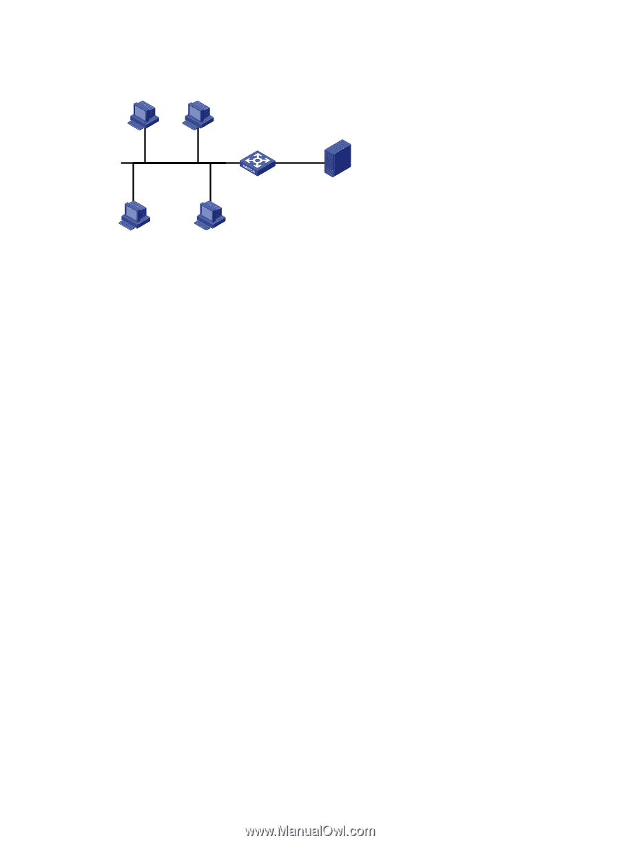
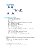
Figure 56 Network diagram DHCPv6 client DHCPv6 client Vlan-int3 1::1/64 Vlan-int2 2::1/64 2::2/64 Switch DHCPv6 server DHCPv6 relay agent DHCPv6 client DHCPv6 client Configuration procedure 1. Configure Switch as a DHCPv6 relay agent: # Enable the IPv6 packet forwarding function. system-view [Switch] ipv6 # Configure the IPv6 addresses of VLAN-interface 2 and VLAN-interface 3 respectively. [Switch] interface vlan-interface 2 [Switch-Vlan-interface2] ipv6 address 2::1 64 [Switch-Vlan-interface2] quit [Switch] interface vlan-interface 3 [Switch-Vlan-interface3] ipv6 address 1::1 64 # Enable DHCPv6 relay agent and specify the DHCPv6 server address on VLAN-interface 3. [Switch-Vlan-interface3] ipv6 dhcp relay server-address 2::2 2. Configure Switch as a gateway: # Enable Switch to send RA messages and turn on the M and O flags. [Switch-Vlan-interface3] undo ipv6 nd ra halt [Switch-Vlan-interface3] ipv6 nd autoconfig managed-address-flag [Switch-Vlan-interface3] ipv6 nd autoconfig other-flag Verifying the configuration # Display address information about DHCPv6 server addresses specified on the DHCPv6 relay agent on Switch. [Switch-Vlan-interface3] display ipv6 dhcp relay server-address all Interface: Vlan3 Server address(es) Output Interface 2::2 # Display packet statistics on the DHCPv6 relay agent. [SwitchA-Vlan-interface3] display ipv6 dhcp relay statistics Packets dropped : 0 Error : 0 Excess of rate limit : 0 113
-
 1
1 -
2
-
3
-
4
-
5
-
6
-
7
-
8
-
9
-
10
-
11
-
12
-
13
-
14
-
15
-
16
-
17
-
18
-
19
-
20
-
21
-
22
-
23
-
24
-
25
-
26
-
27
-
28
-
29
-
30
-
31
-
32
-
33
-
34
-
35
-
36
-
37
-
38
-
39
-
40
-
41
-
42
-
43
-
44
-
45
-
46
-
47
-
48
-
49
-
50
-
51
-
52
-
53
-
54
-
55
-
56
-
57
-
58
-
59
-
60
-
61
-
62
-
63
-
64
-
65
-
66
-
67
-
68
-
69
-
70
-
71
-
72
-
73
-
74
-
75
-
76
-
77
-
78
-
79
-
80
-
81
-
82
-
83
-
84
-
85
-
86
-
87
-
88
-
89
-
90
-
91
-
92
-
93
-
94
-
95
-
96
-
97
-
98
-
99
-
100
-
101
-
102
-
103
-
104
-
105
-
106
-
107
-
108
-
109
-
110
-
111
-
112
-
113
-
114
-
115
-
 116
116 -
 117
117 -
 118
118 -
 119
119 -
 120
120 -
 121
121 -
 122
122 -
 123
123 -
 124
124 -
 125
125 -
 126
126 -
127
-
128
-
129
-
130
-
131
-
132
-
133
-
134
-
135
-
136
-
137
-
138
-
139
-
140
-
141
-
142
-
143
-
144
-
145
-
146
-
147
-
148
-
149
-
150
-
151
-
152
-
153
-
154
-
155
-
156
-
157
-
158
-
159
-
160
-
161
-
162
-
163
-
164
-
165
 |
 |