HP 6125G HP 6125G & 6125G/XG Blade Switches Layer 3 - IP Services Conf - Page 20
Configuring proxy ARP, Overview, Common proxy ARP, Local proxy ARP
 |
View all HP 6125G manuals
Add to My Manuals
Save this manual to your list of manuals |
Page 20 highlights
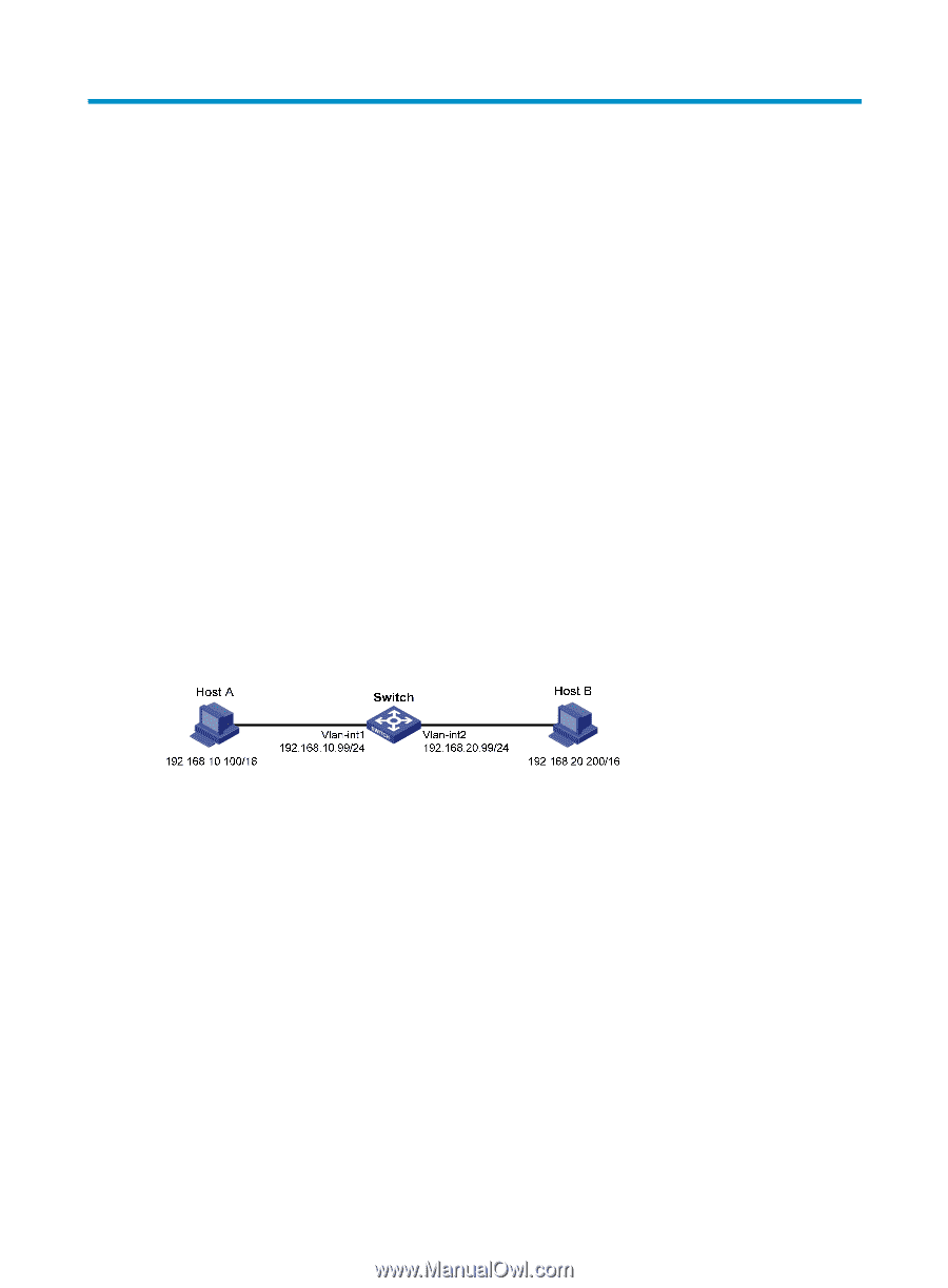
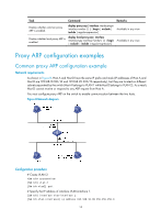
Configuring proxy ARP Overview Proxy ARP enables a device on a network to answer ARP requests for an IP address not on that network. With proxy ARP, hosts on different broadcast domains can communicate with each other as they do on the same network. Proxy ARP includes common proxy ARP and local proxy ARP. • Common proxy ARP-Allows communication between hosts that connect to different Layer-3 interfaces and reside in different broadcast domains. • Local proxy ARP-Allows communication between hosts that connect to the same Layer-3 interface and reside in different broadcast domains. Common proxy ARP A common proxy ARP enabled device allows hosts that reside on different subnets to communicate. As shown in Figure 6, Switch connects to two subnets through VLAN-interface 1 and VLAN-interface 2. The IP addresses of the two interfaces are 192.168.10.99/24 and 192.168.20.99/24. Host A and Host B are assigned the same prefix 192.168.0.0. Host A connects to VLAN-interface 1 and Host B connects to VLAN-interface 2. Figure 6 Application environment of common proxy ARP Because Host A and Host B have the same prefix 192.168.0.0, Host A considers that Host B is on the same network, and it broadcasts an ARP request for the MAC address of Host B. However, Host B cannot receive this request because it is in a different broadcast domain. You can common enable proxy ARP on VLAN-interface 1 of the switch so that the switch can reply to the ARP request from Host A with the MAC address of VLAN-interface 1, and forward packets sent from Host A to Host B. In this case, the switch acts as a proxy of Host B. A main advantage of common proxy ARP is that you can enable it on a single switch without disturbing routing tables of other routers in the network. Proxy ARP acts as the gateway for hosts that are not configured with a default gateway or do not have routing capability. Local proxy ARP As shown in Figure 7, Host A and Host B belong to VLAN 2, but are isolated at Layer 2. Host A connects to GigabitEthernet 1/0/3 while Host B connects to GigabitEthernet 1/0/1. Enable local proxy ARP on Switch A to allow Layer 3 communication between the two hosts. 12
-
 1
1 -
2
-
3
-
4
-
5
-
6
-
7
-
8
-
9
-
10
-
11
-
12
-
13
-
14
-
 15
15 -
 16
16 -
 17
17 -
 18
18 -
 19
19 -
 20
20 -
 21
21 -
 22
22 -
 23
23 -
 24
24 -
 25
25 -
26
-
27
-
28
-
29
-
30
-
31
-
32
-
33
-
34
-
35
-
36
-
37
-
38
-
39
-
40
-
41
-
42
-
43
-
44
-
45
-
46
-
47
-
48
-
49
-
50
-
51
-
52
-
53
-
54
-
55
-
56
-
57
-
58
-
59
-
60
-
61
-
62
-
63
-
64
-
65
-
66
-
67
-
68
-
69
-
70
-
71
-
72
-
73
-
74
-
75
-
76
-
77
-
78
-
79
-
80
-
81
-
82
-
83
-
84
-
85
-
86
-
87
-
88
-
89
-
90
-
91
-
92
-
93
-
94
-
95
-
96
-
97
-
98
-
99
-
100
-
101
-
102
-
103
-
104
-
105
-
106
-
107
-
108
-
109
-
110
-
111
-
112
-
113
-
114
-
115
-
116
-
117
-
118
-
119
-
120
-
121
-
122
-
123
-
124
-
125
-
126
-
127
-
128
-
129
-
130
-
131
-
132
-
133
-
134
-
135
-
136
-
137
-
138
-
139
-
140
-
141
-
142
-
143
-
144
-
145
-
146
-
147
-
148
-
149
-
150
-
151
-
152
-
153
-
154
-
155
-
156
-
157
-
158
-
159
-
160
-
161
-
162
-
163
-
164
-
165
 |
 |