HP 6125G HP 6125G & 6125G/XG Blade Switches Layer 3 - IP Services Conf - Page 16
Multicast ARP configuration example, Network requirements
 |
View all HP 6125G manuals
Add to My Manuals
Save this manual to your list of manuals |
Page 16 highlights
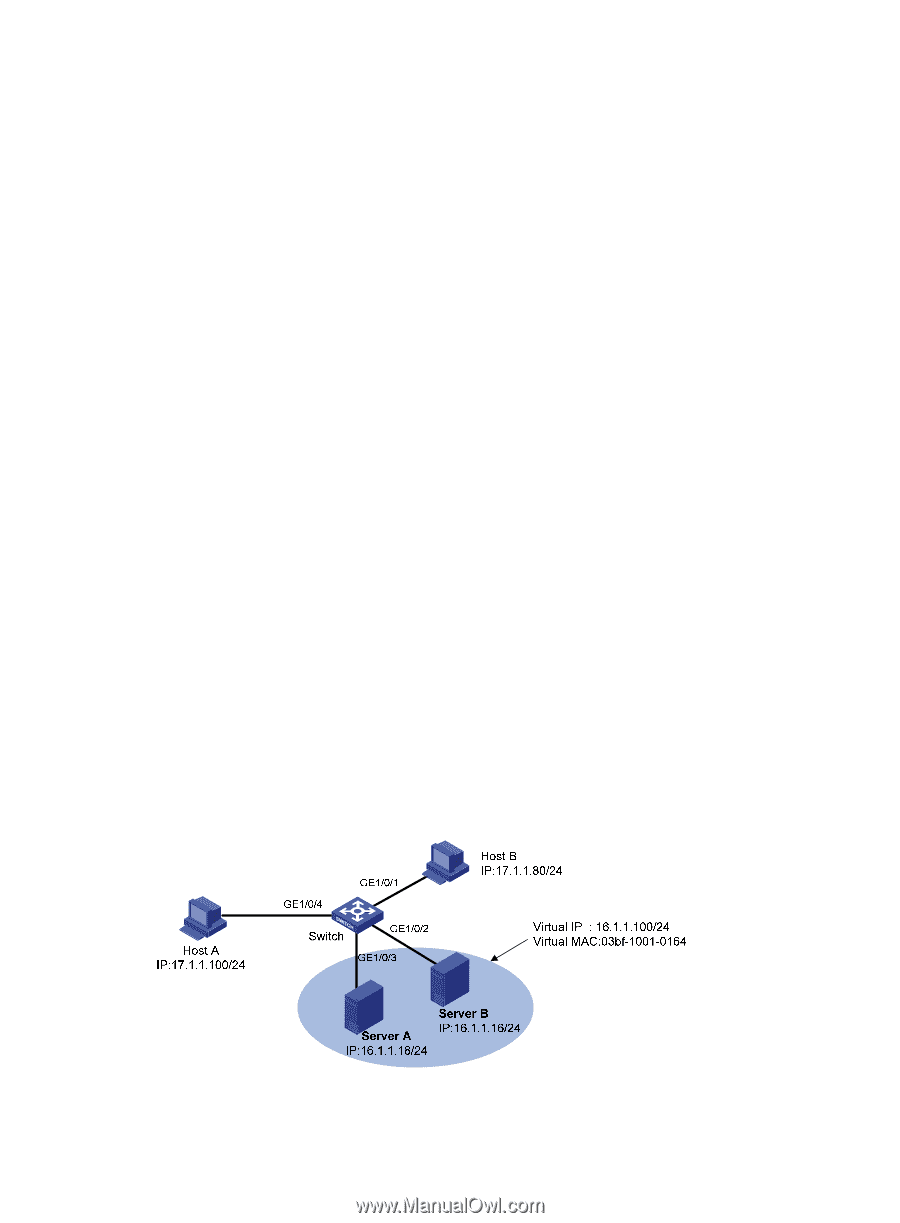
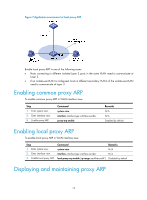
[Switch-GigabitEthernet1/0/1] port link-type trunk [Switch-GigabitEthernet1/0/1] port trunk permit vlan 10 [Switch-GigabitEthernet1/0/1] quit # Create interface VLAN-interface 10 and configure its IP address. [Switch] interface vlan-interface 10 [Switch-vlan-interface10] ip address 192.168.1.2 24 [Switch-vlan-interface10] quit # Configure a static ARP entry that has IP address 192.168.1.1, MAC address 00e0-fc01-0000, and output interface GigabitEthernet 1/0/1 in VLAN 10. [Switch] arp static 192.168.1.1 00e0-fc01-0000 10 GigabitEthernet 1/0/1 # Display information about static ARP entries. [Switch] display arp static Type: S-Static D-Dynamic A-Authorized IP Address MAC Address VLAN ID Interface 192.168.1.1 00e0-fc01-0000 10 GE1/0/1 Aging Type N/A S Multicast ARP configuration example Network requirements As shown in Figure 5, a small data center uses Microsoft multicast-mode NLB. To enable the switches to cooperate with NLB, configure the following: • Add GigabitEthernet 1/0/2 and GigabitEthernet 1/0/3 into VLAN 1, and specify IP address 16.1.1.30/24 for VLAN-interface 1. • Add GigabitEthernet 1/0/1 and GigabitEthernet 1/0/4 into VLAN 2, and specify IP address 17.1.1.1/24 for VLAN-interface 2. • Specify 17.1.1.1/24 as the default gateway of Host A and Host B. • Specify 16.1.1.30/24 as the default gateway of Server A and Server B. • Disable the ARP entry check function so that the switch can learn dynamic ARP entries containing multicast MAC addresses. • Configure a static multicast MAC address entry so that only interfaces GigabitEthernet 1/0/2 and GigabitEthernet 1/0/3 can receive multicast information. Figure 5 Network diagram 8
-
 1
1 -
2
-
3
-
4
-
5
-
6
-
7
-
8
-
9
-
10
-
 11
11 -
 12
12 -
 13
13 -
 14
14 -
 15
15 -
 16
16 -
 17
17 -
 18
18 -
 19
19 -
 20
20 -
 21
21 -
22
-
23
-
24
-
25
-
26
-
27
-
28
-
29
-
30
-
31
-
32
-
33
-
34
-
35
-
36
-
37
-
38
-
39
-
40
-
41
-
42
-
43
-
44
-
45
-
46
-
47
-
48
-
49
-
50
-
51
-
52
-
53
-
54
-
55
-
56
-
57
-
58
-
59
-
60
-
61
-
62
-
63
-
64
-
65
-
66
-
67
-
68
-
69
-
70
-
71
-
72
-
73
-
74
-
75
-
76
-
77
-
78
-
79
-
80
-
81
-
82
-
83
-
84
-
85
-
86
-
87
-
88
-
89
-
90
-
91
-
92
-
93
-
94
-
95
-
96
-
97
-
98
-
99
-
100
-
101
-
102
-
103
-
104
-
105
-
106
-
107
-
108
-
109
-
110
-
111
-
112
-
113
-
114
-
115
-
116
-
117
-
118
-
119
-
120
-
121
-
122
-
123
-
124
-
125
-
126
-
127
-
128
-
129
-
130
-
131
-
132
-
133
-
134
-
135
-
136
-
137
-
138
-
139
-
140
-
141
-
142
-
143
-
144
-
145
-
146
-
147
-
148
-
149
-
150
-
151
-
152
-
153
-
154
-
155
-
156
-
157
-
158
-
159
-
160
-
161
-
162
-
163
-
164
-
165
 |
 |