HP 6125G HP 6125G & 6125G/XG Blade Switches Layer 3 - IP Services Conf - Page 144
Network diagram
 |
View all HP 6125G manuals
Add to My Manuals
Save this manual to your list of manuals |
Page 144 highlights
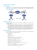
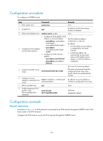
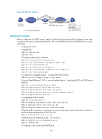
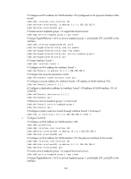
Figure 66 Network diagram IPv6 host 3002::2/64 Switch ISATAP switch Vlan-int100 Vlan-int101 IPv6 network 3001::1/64 1.1.1.1/8 IPv4 network ISATAP tunnel GE1/0/3 Tunnel0 2001::5EFE:0101:0101/64 Service loopack port ISATAP host IPv4 address:2.1.1.2/32 IPv6 address: FE80::5EFE:0201:0102 2001::5EFE:0201:0102 Configuration procedure Before configuring an ISATAP tunnel, make sure that the corresponding VLAN interfaces have been created on the switch, and that VLAN-interface 101 on the ISATAP switch and the ISATAP host can reach each other. • Configure the switch: # Enable IPv6. system-view [Switch] ipv6 # Configure addresses for interfaces. [Switch] interface vlan-interface 100 [Switch-Vlan-interface100] ipv6 address 3001::1/64 [Switch-Vlan-interface100] quit [Switch] interface vlan-interface 101 [Switch-Vlan-interface101] ip address 1.1.1.1 255.0.0.0 [Switch-Vlan-interface101] quit # Create service loopback group 1 to support the tunnel service. [Switch] service-loopback group 1 type tunnel # Assign GigabitEthernet 1/0/3 to service loopback group 1, and disable STP, and LLDP on the interface. [Switch] interface GigabitEthernet 1/0/3 [Switch-GigabitEthernet1/0/3] undo stp enable [Switch-GigabitEthernet1/0/3] undo lldp enable [Switch-GigabitEthernet1/0/3] port service-loopback group 1 [Switch-GigabitEthernet1/0/3] quit # Configure an ISATAP tunnel. [Switch] interface tunnel 0 [Switch-Tunnel0] ipv6 address 2001::5efe:0101:0101 64 [Switch-Tunnel0] source vlan-interface 101 [Switch-Tunnel0] tunnel-protocol ipv6-ipv4 isatap # Disable the RA suppression so that hosts can acquire information such as the address prefix from the RA message released by the ISATAP switch. [Switch-Tunnel0] undo ipv6 nd ra halt # Reference service loopback group 1 on the tunnel. [Switch-Tunnel0] service-loopback-group 1 [Switch-Tunnel0] quit # Configure a static route to the ISATAP host. 136
-
 1
1 -
2
-
3
-
4
-
5
-
6
-
7
-
8
-
9
-
10
-
11
-
12
-
13
-
14
-
15
-
16
-
17
-
18
-
19
-
20
-
21
-
22
-
23
-
24
-
25
-
26
-
27
-
28
-
29
-
30
-
31
-
32
-
33
-
34
-
35
-
36
-
37
-
38
-
39
-
40
-
41
-
42
-
43
-
44
-
45
-
46
-
47
-
48
-
49
-
50
-
51
-
52
-
53
-
54
-
55
-
56
-
57
-
58
-
59
-
60
-
61
-
62
-
63
-
64
-
65
-
66
-
67
-
68
-
69
-
70
-
71
-
72
-
73
-
74
-
75
-
76
-
77
-
78
-
79
-
80
-
81
-
82
-
83
-
84
-
85
-
86
-
87
-
88
-
89
-
90
-
91
-
92
-
93
-
94
-
95
-
96
-
97
-
98
-
99
-
100
-
101
-
102
-
103
-
104
-
105
-
106
-
107
-
108
-
109
-
110
-
111
-
112
-
113
-
114
-
115
-
116
-
117
-
118
-
119
-
120
-
121
-
122
-
123
-
124
-
125
-
126
-
127
-
128
-
129
-
130
-
131
-
132
-
133
-
134
-
135
-
136
-
137
-
138
-
 139
139 -
 140
140 -
 141
141 -
 142
142 -
 143
143 -
 144
144 -
 145
145 -
 146
146 -
 147
147 -
 148
148 -
 149
149 -
150
-
151
-
152
-
153
-
154
-
155
-
156
-
157
-
158
-
159
-
160
-
161
-
162
-
163
-
164
-
165
 |
 |