HP 6125G HP 6125G & 6125G/XG Blade Switches Layer 3 - IP Services Conf - Page 85
Displaying and maintaining UDP helper, UDP helper configuration example, Network requirements,
 |
View all HP 6125G manuals
Add to My Manuals
Save this manual to your list of manuals |
Page 85 highlights
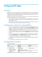
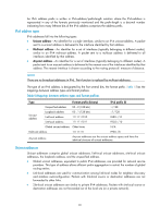
Step Command 4. Enter interface view. interface interface-type interface-number 5. Specify the destination server to which UDP packets are to udp-helper server [ vpn-instance be forwarded. vpn-instance-name ] ip-address Remarks N/A No destination server is specified by default. Displaying and maintaining UDP helper Task Displays information about forwarded UDP packets. Clear statistics about packets forwarded. Command Remarks display udp-helper server [ interface interface-type interface-number ] [ | { begin Available in any view | exclude | include } regular-expression ] reset udp-helper packet Available in user view UDP helper configuration example Network requirements As shown in Figure 42, the IP address of VLAN-interface 1 of Switch A is 10.110.1.1/16, and the interface connects to the subnet 10.110.0.0/16. Configure UDP helper to forward broadcast packets with UDP destination port number 55 and destination IP address 255.255.255.255 or 10.110.255.255 to the destination server 10.2.1.1/16 in public network. Figure 42 Network diagram Vlan-int1 10.110.1.1/16 Switch A Vlan-int1 Server 10.2.1.1/16 IP network Switch B Configuration procedure Verify that a route from Switch A to the subnet 10.2.0.0/16 is available. # Enable Switch A to receive directed broadcasts. system-view [SwitchA] ip forward-broadcast # Enable UDP helper. [SwitchA] udp-helper enable 77
-
 1
1 -
2
-
3
-
4
-
5
-
6
-
7
-
8
-
9
-
10
-
11
-
12
-
13
-
14
-
15
-
16
-
17
-
18
-
19
-
20
-
21
-
22
-
23
-
24
-
25
-
26
-
27
-
28
-
29
-
30
-
31
-
32
-
33
-
34
-
35
-
36
-
37
-
38
-
39
-
40
-
41
-
42
-
43
-
44
-
45
-
46
-
47
-
48
-
49
-
50
-
51
-
52
-
53
-
54
-
55
-
56
-
57
-
58
-
59
-
60
-
61
-
62
-
63
-
64
-
65
-
66
-
67
-
68
-
69
-
70
-
71
-
72
-
73
-
74
-
75
-
76
-
77
-
78
-
79
-
 80
80 -
 81
81 -
 82
82 -
 83
83 -
 84
84 -
 85
85 -
 86
86 -
 87
87 -
 88
88 -
 89
89 -
 90
90 -
91
-
92
-
93
-
94
-
95
-
96
-
97
-
98
-
99
-
100
-
101
-
102
-
103
-
104
-
105
-
106
-
107
-
108
-
109
-
110
-
111
-
112
-
113
-
114
-
115
-
116
-
117
-
118
-
119
-
120
-
121
-
122
-
123
-
124
-
125
-
126
-
127
-
128
-
129
-
130
-
131
-
132
-
133
-
134
-
135
-
136
-
137
-
138
-
139
-
140
-
141
-
142
-
143
-
144
-
145
-
146
-
147
-
148
-
149
-
150
-
151
-
152
-
153
-
154
-
155
-
156
-
157
-
158
-
159
-
160
-
161
-
162
-
163
-
164
-
165
 |
 |