HP 6125G HP 6125G & 6125G/XG Blade Switches Layer 3 - IP Services Conf - Page 79
Configuration example, Network requirements, Configuration procedure, Configuring TCP attributes
 |
View all HP 6125G manuals
Add to My Manuals
Save this manual to your list of manuals |
Page 79 highlights
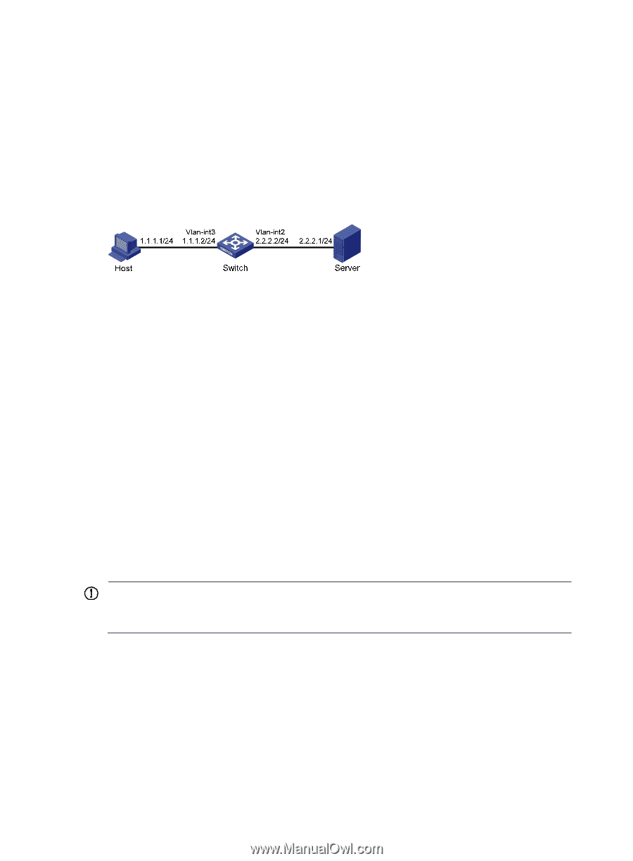
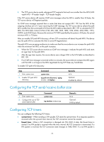
Configuration example Network requirements As shown in Figure 41, the host's interface and VLAN-interface 3 of the switch are on the same network segment (1.1.1.0/24). VLAN-interface 2 of Switch and the server are on another network segment (2.2.2.0/24). The default gateway of the host is VLAN-interface 3 (IP address 1.1.1.2/24) of Switch. Configure the switch so that the server can receive directed broadcasts from the host to IP address 2.2.2.255. Figure 41 Network diagram Configuration procedure # Enable the switch to receive directed broadcasts. system-view [Switch] ip forward-broadcast # Configure IP addresses for VLAN-interface 3 and VLAN-interface 2. [Switch] interface vlan-interface 3 [Switch-Vlan-interface3] ip address 1.1.1.2 24 [Switch-Vlan-interface3] quit [Switch] interface vlan-interface 2 [Switch-Vlan-interface2] ip address 2.2.2.2 24 # Enable VLAN-interface 2 to forward directed broadcasts. [Switch-Vlan-interface2] ip forward-broadcast Configuring TCP attributes Configuring TCP path MTU discovery IMPORTANT: All the devices on the TCP path must be enabled to send ICMP error messages by using the ip unreachables enable command. TCP path MTU discovery (in RFC 1191) discovers the path MTU between the source and destination ends of a TCP connection. It works as follows: 1. A TCP source device sends a packet with the Don't Fragment (DF) bit set. 2. A router that fails to forward the packet because it exceeds the MTU on the outgoing interface discards the packet and returns an ICMP error message, which contains the MTU of the outgoing interface. 3. Upon receiving the ICMP message, the TCP source device calculates the current path MTU of the TCP connection. 71
-
 1
1 -
2
-
3
-
4
-
5
-
6
-
7
-
8
-
9
-
10
-
11
-
12
-
13
-
14
-
15
-
16
-
17
-
18
-
19
-
20
-
21
-
22
-
23
-
24
-
25
-
26
-
27
-
28
-
29
-
30
-
31
-
32
-
33
-
34
-
35
-
36
-
37
-
38
-
39
-
40
-
41
-
42
-
43
-
44
-
45
-
46
-
47
-
48
-
49
-
50
-
51
-
52
-
53
-
54
-
55
-
56
-
57
-
58
-
59
-
60
-
61
-
62
-
63
-
64
-
65
-
66
-
67
-
68
-
69
-
70
-
71
-
72
-
73
-
 74
74 -
 75
75 -
 76
76 -
 77
77 -
 78
78 -
 79
79 -
 80
80 -
 81
81 -
 82
82 -
 83
83 -
 84
84 -
85
-
86
-
87
-
88
-
89
-
90
-
91
-
92
-
93
-
94
-
95
-
96
-
97
-
98
-
99
-
100
-
101
-
102
-
103
-
104
-
105
-
106
-
107
-
108
-
109
-
110
-
111
-
112
-
113
-
114
-
115
-
116
-
117
-
118
-
119
-
120
-
121
-
122
-
123
-
124
-
125
-
126
-
127
-
128
-
129
-
130
-
131
-
132
-
133
-
134
-
135
-
136
-
137
-
138
-
139
-
140
-
141
-
142
-
143
-
144
-
145
-
146
-
147
-
148
-
149
-
150
-
151
-
152
-
153
-
154
-
155
-
156
-
157
-
158
-
159
-
160
-
161
-
162
-
163
-
164
-
165
 |
 |