HP 6125G HP 6125G & 6125G/XG Blade Switches Layer 3 - IP Services Conf - Page 146
Verifying the configuration, Configuring an IPv4 over IPv4 tunnel, Configuration prerequisites,
 |
View all HP 6125G manuals
Add to My Manuals
Save this manual to your list of manuals |
Page 146 highlights
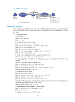
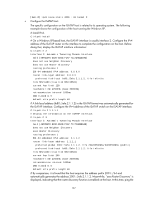
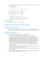
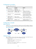
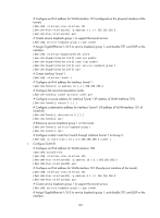
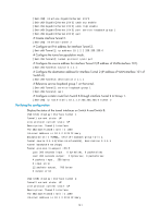
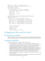
IPv6 address of the tunnel interface of the switch. If the address is successfully pinged, an ISATAP tunnel is established. C:\>ping 2001::5efe:1.1.1.1 Pinging 2001::5efe:1.1.1.1 with 32 bytes of data: Reply from 2001::5efe:1.1.1.1: time=1ms Reply from 2001::5efe:1.1.1.1: time=1ms Reply from 2001::5efe:1.1.1.1: time=1ms Reply from 2001::5efe:1.1.1.1: time=1ms Ping statistics for 2001::5efe:1.1.1.1: Packets: Sent = 4, Received = 4, Lost = 0 (0% loss), Approximate round trip times in milli-seconds: Minimum = 1ms, Maximum = 1ms, Average = 1ms Verifying the configuration The ISATAP host can access the host in the IPV6 network. Configuring an IPv4 over IPv4 tunnel Configuration prerequisites Configure IP addresses for interfaces (such as the VLAN interface, and loopback interface) on the device to ensure normal communication. One of the interfaces will be used as the source interface of the tunnel. Configuration guidelines Follow these guidelines when you configure an IPv4 over IPv4 tunnel: • The tunnel source end and destination end must be public addresses or interfaces. • To encapsulate and forward IPv4 packets whose destination address does not belong to the subnet where the receiving tunnel interface resides, configure a static route or dynamic routing for forwarding those packets through this tunnel interface. If you configure a static route to that destination IPv4 address, specify this tunnel interface as the outbound interface, or the peer tunnel interface address as the next hop. A similar configuration is required at the other tunnel end. If you configure dynamic routing at both ends, enable the dynamic routing protocol on both tunnel interfaces. For the detailed configuration, see Layer 3-IP Routing Configuration Guide. • The IPv4 address of the local tunnel interface cannot be on the same subnet as the destination address of the tunnel. • The destination address of a route with a tunnel interface as the egress interface must not be on the same subnet as the destination address of the tunnel. • Two or more tunnel interfaces using the same encapsulation protocol must have different source and destination addresses. • If you specify a source interface instead of a source address for the tunnel, the source address of the tunnel is the primary IP address of the source interface. 138
-
 1
1 -
2
-
3
-
4
-
5
-
6
-
7
-
8
-
9
-
10
-
11
-
12
-
13
-
14
-
15
-
16
-
17
-
18
-
19
-
20
-
21
-
22
-
23
-
24
-
25
-
26
-
27
-
28
-
29
-
30
-
31
-
32
-
33
-
34
-
35
-
36
-
37
-
38
-
39
-
40
-
41
-
42
-
43
-
44
-
45
-
46
-
47
-
48
-
49
-
50
-
51
-
52
-
53
-
54
-
55
-
56
-
57
-
58
-
59
-
60
-
61
-
62
-
63
-
64
-
65
-
66
-
67
-
68
-
69
-
70
-
71
-
72
-
73
-
74
-
75
-
76
-
77
-
78
-
79
-
80
-
81
-
82
-
83
-
84
-
85
-
86
-
87
-
88
-
89
-
90
-
91
-
92
-
93
-
94
-
95
-
96
-
97
-
98
-
99
-
100
-
101
-
102
-
103
-
104
-
105
-
106
-
107
-
108
-
109
-
110
-
111
-
112
-
113
-
114
-
115
-
116
-
117
-
118
-
119
-
120
-
121
-
122
-
123
-
124
-
125
-
126
-
127
-
128
-
129
-
130
-
131
-
132
-
133
-
134
-
135
-
136
-
137
-
138
-
139
-
140
-
 141
141 -
 142
142 -
 143
143 -
 144
144 -
 145
145 -
 146
146 -
 147
147 -
 148
148 -
 149
149 -
 150
150 -
 151
151 -
152
-
153
-
154
-
155
-
156
-
157
-
158
-
159
-
160
-
161
-
162
-
163
-
164
-
165
 |
 |