HP 6125G HP 6125G & 6125G/XG Blade Switches Layer 3 - IP Services Conf - Page 151
Network diagram
 |
View all HP 6125G manuals
Add to My Manuals
Save this manual to your list of manuals |
Page 151 highlights
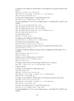
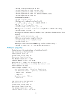
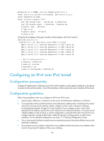
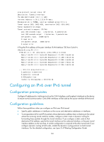
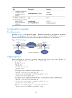
Configuration procedure To configure an IPv4 over IPv6 tunnel: Step 1. Enter system view. 2. Enable IPv6. 3. Enter tunnel interface view. 4. Configure an IPv4 address for the tunnel interface. 5. Specify the IPv4 over IPv6 tunnel mode. 6. Configure the source address or interface for the tunnel interface. 7. Configure the destination address for the tunnel interface. Command system-view ipv6 interface tunnel number ip address ip-address { mask | mask-length } [ sub ] tunnel-protocol ipv4-ipv6 source { ipv6-address | interface-type interface-number } destination ipv6-address Remarks N/A By default, the IPv6 packet forwarding function is disabled. N/A By default, no IPv4 address is configured for the tunnel interface. IPv4 oever IPv4 tunnel by default. The same tunnel mode should be configured at both ends of the tunnel. Otherwise, packet delivery will fail. By default, no source address or interface is configured for the tunnel. By default, no destination address is configured for the tunnel. Configuration example Network requirements As shown in Figure 68, the two subnets Group 1 and Group 2 are connected over an IPv6 network. Configure an IPv4 over IPv6 tunnel between Switch A and Switch B to make the two subnets reachable to each other. Figure 68 Network diagram GE1/0/3 Switch A Vlan-int101 2002::1:1/64 Vlan-int100 30.1.1.1/24 Tunnel1 30.1.2.1/24 IPv6 network IPv4 over IPv6 tunnel Switch B Vlan-int101 2002::2:1/64 GE1/0/3 Tunnel2 30.1.2.2/24 Vlan-int100 30.1.3.1/24 IPv4 Group 1 Service loopback port IPv4 Group 2 Configuration procedure Before configuring an IPv4 over IPv6 tunnel, make sure that Switch A and Switch B have the corresponding VLAN interfaces created and can reach each other. • Configure Switch A: # Enable IPv6. system-view 143
-
 1
1 -
2
-
3
-
4
-
5
-
6
-
7
-
8
-
9
-
10
-
11
-
12
-
13
-
14
-
15
-
16
-
17
-
18
-
19
-
20
-
21
-
22
-
23
-
24
-
25
-
26
-
27
-
28
-
29
-
30
-
31
-
32
-
33
-
34
-
35
-
36
-
37
-
38
-
39
-
40
-
41
-
42
-
43
-
44
-
45
-
46
-
47
-
48
-
49
-
50
-
51
-
52
-
53
-
54
-
55
-
56
-
57
-
58
-
59
-
60
-
61
-
62
-
63
-
64
-
65
-
66
-
67
-
68
-
69
-
70
-
71
-
72
-
73
-
74
-
75
-
76
-
77
-
78
-
79
-
80
-
81
-
82
-
83
-
84
-
85
-
86
-
87
-
88
-
89
-
90
-
91
-
92
-
93
-
94
-
95
-
96
-
97
-
98
-
99
-
100
-
101
-
102
-
103
-
104
-
105
-
106
-
107
-
108
-
109
-
110
-
111
-
112
-
113
-
114
-
115
-
116
-
117
-
118
-
119
-
120
-
121
-
122
-
123
-
124
-
125
-
126
-
127
-
128
-
129
-
130
-
131
-
132
-
133
-
134
-
135
-
136
-
137
-
138
-
139
-
140
-
141
-
142
-
143
-
144
-
145
-
 146
146 -
 147
147 -
 148
148 -
 149
149 -
 150
150 -
 151
151 -
 152
152 -
 153
153 -
 154
154 -
 155
155 -
 156
156 -
157
-
158
-
159
-
160
-
161
-
162
-
163
-
164
-
165
 |
 |