HP 6125G HP 6125G & 6125G/XG Blade Switches Layer 3 - IP Services Conf - Page 15
ARP configuration examples, Static ARP entry configuration example, Network requirements
 |
View all HP 6125G manuals
Add to My Manuals
Save this manual to your list of manuals |
Page 15 highlights
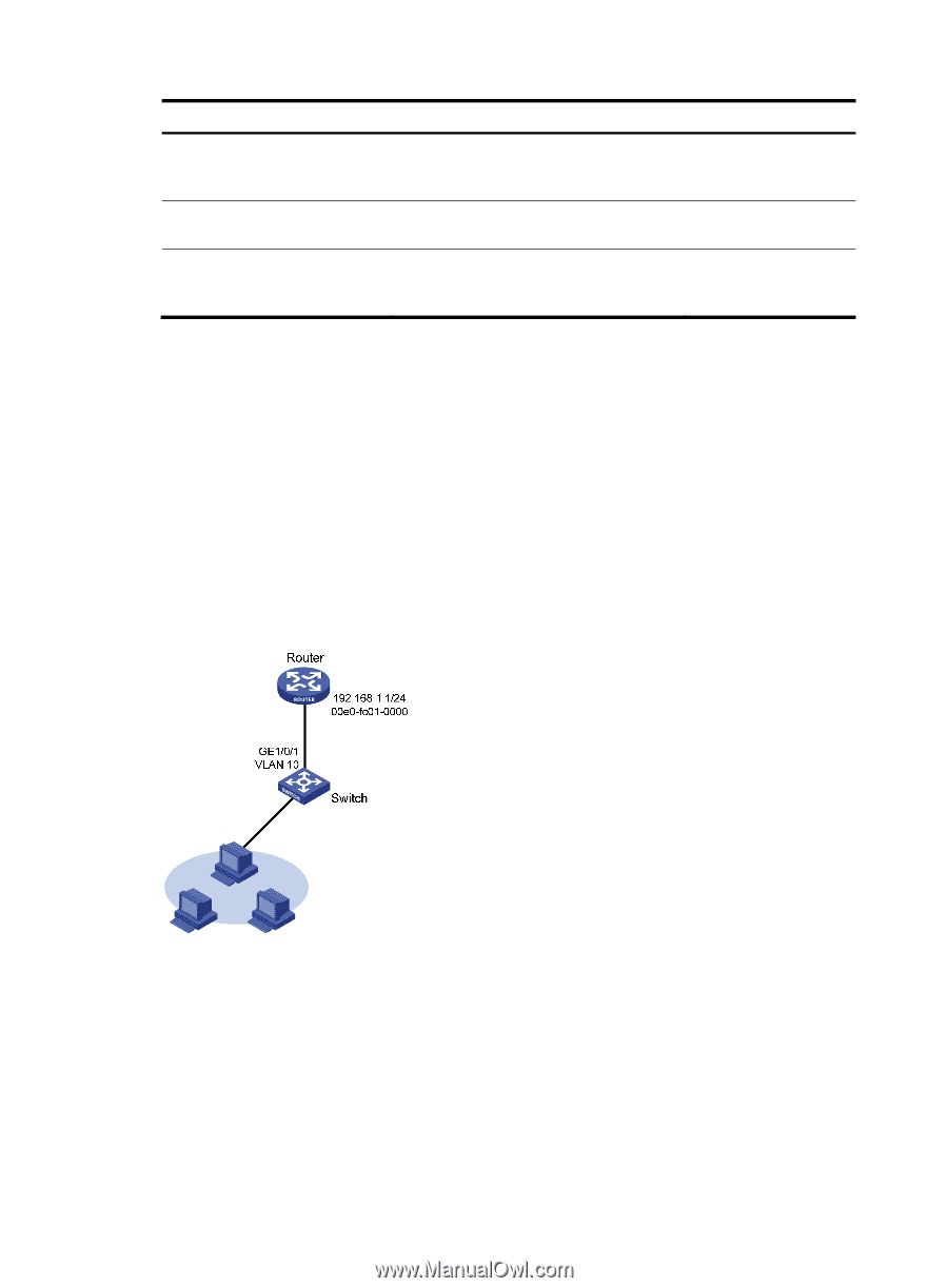
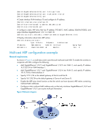
Task Command Remarks Display the ARP entries for a specified VPN instance. display arp vpn-instance vpn-instance-name [ count ] [ | { begin | exclude | include } regular-expression ] Available in any view Display the age timer for dynamic ARP entries. display arp timer aging [ | { begin | exclude | include } regular-expression ] Available in any view Clear ARP entries from the ARP table . reset arp { all | dynamic | static | slot slot-number | interface interface-type interface-number } Available in user view ARP configuration examples Static ARP entry configuration example Network requirements As shown in Figure 4, hosts are connected to the switch, which is connected to the router through interface GigabitEthernet 1/0/1 in VLAN 10. The IP and MAC addresses of the router are 192.168.1.1/24 and 00e0-fc01-0000 respectively. To prevent malicious users from attacking the switch and enhance security for communications between the router and switch, configure a static ARP entry for the router on the switch. Figure 4 Network diagram Configuration procedure Configure the switch: # Create VLAN 10. system-view [Switch] vlan 10 [Switch-vlan10] quit # Add interface GigabitEthernet 1/0/1 to VLAN 10. [Switch] interface GigabitEthernet 1/0/1 7
-
 1
1 -
2
-
3
-
4
-
5
-
6
-
7
-
8
-
9
-
 10
10 -
 11
11 -
 12
12 -
 13
13 -
 14
14 -
 15
15 -
 16
16 -
 17
17 -
 18
18 -
 19
19 -
 20
20 -
21
-
22
-
23
-
24
-
25
-
26
-
27
-
28
-
29
-
30
-
31
-
32
-
33
-
34
-
35
-
36
-
37
-
38
-
39
-
40
-
41
-
42
-
43
-
44
-
45
-
46
-
47
-
48
-
49
-
50
-
51
-
52
-
53
-
54
-
55
-
56
-
57
-
58
-
59
-
60
-
61
-
62
-
63
-
64
-
65
-
66
-
67
-
68
-
69
-
70
-
71
-
72
-
73
-
74
-
75
-
76
-
77
-
78
-
79
-
80
-
81
-
82
-
83
-
84
-
85
-
86
-
87
-
88
-
89
-
90
-
91
-
92
-
93
-
94
-
95
-
96
-
97
-
98
-
99
-
100
-
101
-
102
-
103
-
104
-
105
-
106
-
107
-
108
-
109
-
110
-
111
-
112
-
113
-
114
-
115
-
116
-
117
-
118
-
119
-
120
-
121
-
122
-
123
-
124
-
125
-
126
-
127
-
128
-
129
-
130
-
131
-
132
-
133
-
134
-
135
-
136
-
137
-
138
-
139
-
140
-
141
-
142
-
143
-
144
-
145
-
146
-
147
-
148
-
149
-
150
-
151
-
152
-
153
-
154
-
155
-
156
-
157
-
158
-
159
-
160
-
161
-
162
-
163
-
164
-
165
 |
 |