HP 6125G HP 6125G & 6125G/XG Blade Switches Layer 3 - IP Services Conf - Page 133
Configuring a tunnel interface, Configuration guidelines, Configuration procedure
 |
View all HP 6125G manuals
Add to My Manuals
Save this manual to your list of manuals |
Page 133 highlights
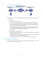
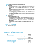
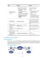
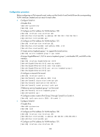
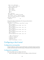
Configuring a tunnel interface Configure a Layer 3 virtual tunnel interface on each device on a tunnel so that devices at both ends can send, identify, and process packets from the tunnel. Configuration guidelines Follow these guidelines when you configure a tunnel interface: • Before configuring a tunnel interface on a switch, you may need create a service loopback group with its service type as Tunnel, and add unused Layer 2 Ethernet interfaces of the switch to the service loopback group. • On the switch, an encapsulated packet cannot be forwarded a second time at Layer 3 by using the destination address and routing table, but is sent to the loopback interface, which then sends the packet to the forwarding module for Layer 3 forwarding. You must reference a service loopback group on the tunnel interface. Otherwise, the tunnel interface will not be up and packets cannot be transmitted over the tunnel. For creation and configuration of a service loopback group, see Layer 2-LAN Switching Configuration Guide. • The tunnel bandwidth command does not change the actual bandwidth of the tunnel interface, but sets a bandwidth value for dynamical routing protocols to calculate the cost of a tunnel path. You can determine the value according to the bandwidth of the output interface. • You must configure a MTU no smaller than 1280 bytes for the tunnel (such as an IPv6 over IPv4 tunnel or an IPv6 over IPv6 tunnel). Configuration procedure To configure a tunnel interface: Step 1. Enter system view. 2. Create a tunnel interface and enter its view. Command system-view interface tunnel number 3. Configure the description for the interface. description text 4. Reference a service loopback group. service-loopback-group number 5. Set the MTU of the tunnel interface. mtu mtu-size Remarks N/A By default, no tunnel interface is created. Optional. By default, the description of a tunnel interface is Tunnelnumber Interface. By default, the tunnel does not reference any service loopback group. Optional. 64000 bytes by default. • An MTU set on any tunnel interface is effective on all existing tunnel interfaces. • You can issue this command multiple times, but only the last configuration takes effect. 125
-
 1
1 -
2
-
3
-
4
-
5
-
6
-
7
-
8
-
9
-
10
-
11
-
12
-
13
-
14
-
15
-
16
-
17
-
18
-
19
-
20
-
21
-
22
-
23
-
24
-
25
-
26
-
27
-
28
-
29
-
30
-
31
-
32
-
33
-
34
-
35
-
36
-
37
-
38
-
39
-
40
-
41
-
42
-
43
-
44
-
45
-
46
-
47
-
48
-
49
-
50
-
51
-
52
-
53
-
54
-
55
-
56
-
57
-
58
-
59
-
60
-
61
-
62
-
63
-
64
-
65
-
66
-
67
-
68
-
69
-
70
-
71
-
72
-
73
-
74
-
75
-
76
-
77
-
78
-
79
-
80
-
81
-
82
-
83
-
84
-
85
-
86
-
87
-
88
-
89
-
90
-
91
-
92
-
93
-
94
-
95
-
96
-
97
-
98
-
99
-
100
-
101
-
102
-
103
-
104
-
105
-
106
-
107
-
108
-
109
-
110
-
111
-
112
-
113
-
114
-
115
-
116
-
117
-
118
-
119
-
120
-
121
-
122
-
123
-
124
-
125
-
126
-
127
-
 128
128 -
 129
129 -
 130
130 -
 131
131 -
 132
132 -
 133
133 -
 134
134 -
 135
135 -
 136
136 -
 137
137 -
 138
138 -
139
-
140
-
141
-
142
-
143
-
144
-
145
-
146
-
147
-
148
-
149
-
150
-
151
-
152
-
153
-
154
-
155
-
156
-
157
-
158
-
159
-
160
-
161
-
162
-
163
-
164
-
165
 |
 |