HP 6125G HP 6125G & 6125G/XG Blade Switches Layer 3 - IP Services Conf - Page 135
Configuration example, Network requirements
 |
View all HP 6125G manuals
Add to My Manuals
Save this manual to your list of manuals |
Page 135 highlights
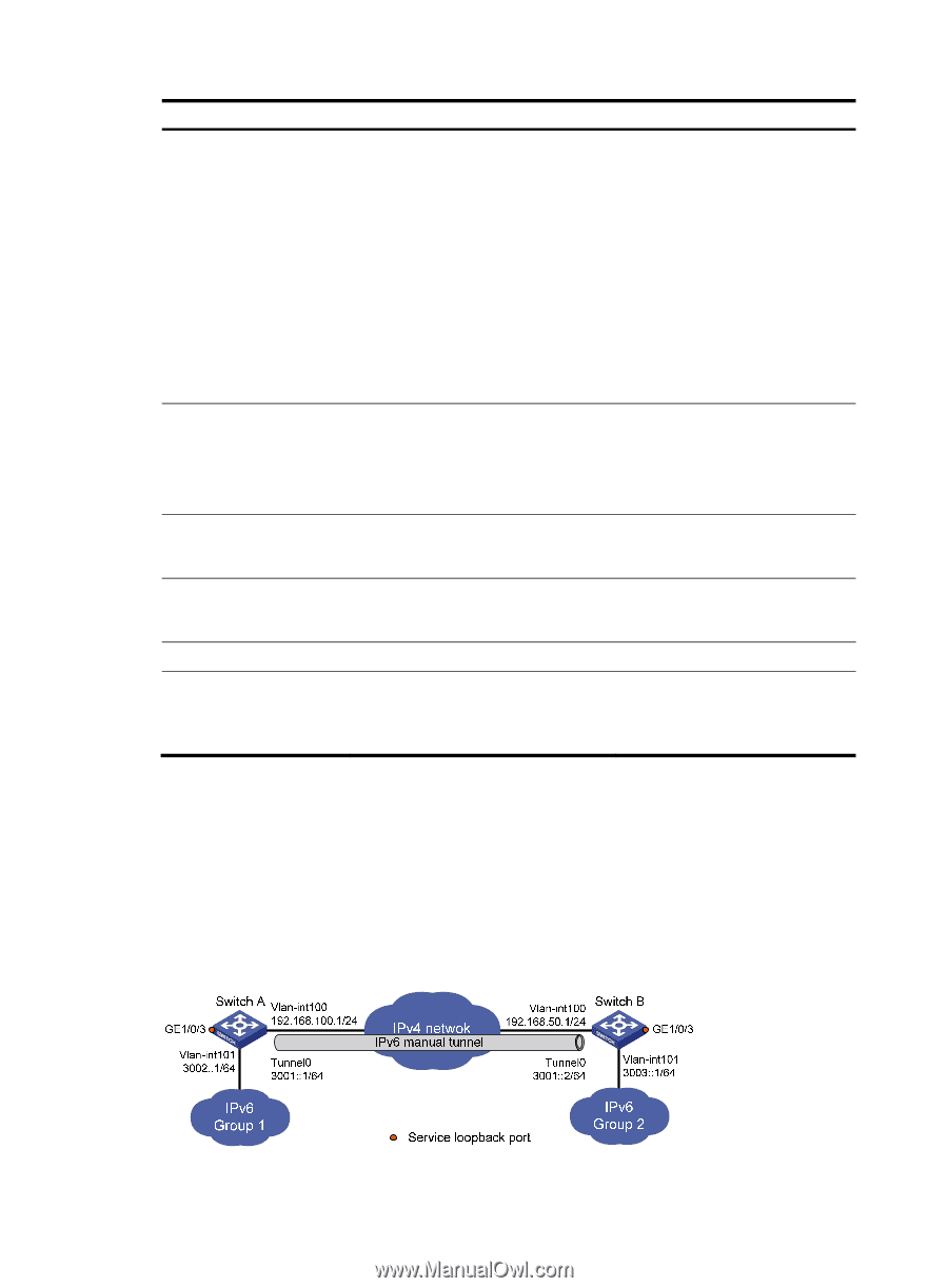
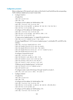
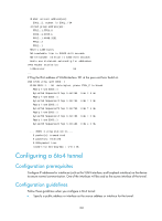
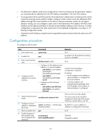
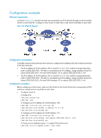
Step Command Remarks 4. Configure an IPv6 address for the tunnel interface. • Configure a global unicast IPv6 address or a site-local address: { ipv6 address { ipv6-address prefix-length | ipv6-address/prefix-length } { ipv6 address ipv6-address/prefix-length eui-64 • Configure a link-local IPv6 address: { ipv6 address auto link-local { ipv6 address ipv6-address link-local The link-local IPv6 address configuration is optional. By default: • No IPv6 global unicast address or site-local address is configured for the tunnel interface. • A link-local address is automatically created when an IPv6 global unicast address or site-local address is configured. 5. Specify the IPv6 manual tunnel mode. tunnel-protocol ipv6-ipv4 6. Configure a source address or interface for source { ip-address | interface-type the tunnel. interface-number } 7. Configure a destination address for destination ip-address the tunnel. 8. Return to system view. quit 9. Enable dropping of IPv6 packets using IPv4-compatible IPv6 addresses. tunnel discard ipv4-compatible-packet IPv4 over IPv4 tunnel by default. The same tunnel mode should be configured at both ends of the tunnel. Otherwise, packet delivery will fail. By default, no source address or interface is configured for the tunnel. By default, no destination address is configured for the tunnel. N/A Optional. Disabled by default. Configuration example Network requirements As shown in Figure 64, two IPv6 networks are connected over an IPv4 network. Configure an IPv6 over IPv4 tunnel between Switch A and Switch B to make the two IPv6 networks reachable to each other. If the destination IPv4 address cannot be automatically obtained from the destination IPv6 addresses of packets, configure an IPv6 manual tunnel. Figure 64 Network diagram 127
-
 1
1 -
2
-
3
-
4
-
5
-
6
-
7
-
8
-
9
-
10
-
11
-
12
-
13
-
14
-
15
-
16
-
17
-
18
-
19
-
20
-
21
-
22
-
23
-
24
-
25
-
26
-
27
-
28
-
29
-
30
-
31
-
32
-
33
-
34
-
35
-
36
-
37
-
38
-
39
-
40
-
41
-
42
-
43
-
44
-
45
-
46
-
47
-
48
-
49
-
50
-
51
-
52
-
53
-
54
-
55
-
56
-
57
-
58
-
59
-
60
-
61
-
62
-
63
-
64
-
65
-
66
-
67
-
68
-
69
-
70
-
71
-
72
-
73
-
74
-
75
-
76
-
77
-
78
-
79
-
80
-
81
-
82
-
83
-
84
-
85
-
86
-
87
-
88
-
89
-
90
-
91
-
92
-
93
-
94
-
95
-
96
-
97
-
98
-
99
-
100
-
101
-
102
-
103
-
104
-
105
-
106
-
107
-
108
-
109
-
110
-
111
-
112
-
113
-
114
-
115
-
116
-
117
-
118
-
119
-
120
-
121
-
122
-
123
-
124
-
125
-
126
-
127
-
128
-
129
-
 130
130 -
 131
131 -
 132
132 -
 133
133 -
 134
134 -
 135
135 -
 136
136 -
 137
137 -
 138
138 -
 139
139 -
 140
140 -
141
-
142
-
143
-
144
-
145
-
146
-
147
-
148
-
149
-
150
-
151
-
152
-
153
-
154
-
155
-
156
-
157
-
158
-
159
-
160
-
161
-
162
-
163
-
164
-
165
 |
 |