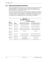
HP Dc7700 HP Compaq dx7300 and dc7700 Business PC Technical Reference Guide, 1 - Page 101
USB Data Formats
 |
UPC - 882780715318
View all HP Dc7700 manuals
Add to My Manuals
Save this manual to your list of manuals |
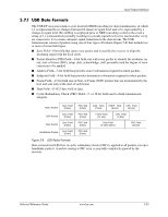
Page 101 highlights
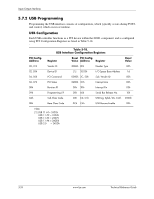
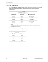
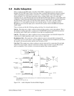
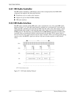
Input/Output Interfaces 5.7.1 USB Data Formats The USB I/F uses non-return-to-zero inverted (NRZI) encoding for data transmissions, in which a 1 is represented by no change (between bit times) in signal level and a 0 is represented by a change in signal level. Bit stuffing is employed prior to NRZ1 encoding so that in the event a string of 1's is transmitted (normally resulting in a steady signal level) a 0 is inserted after every six consecutive 1's to ensure adequate signal transitions in the data stream. The USB transmissions consist of packets using one of four types of formats (Figure 5-8) that include two or more of seven field types. ■ Sync Field-8-bit field that starts every packet and is used by the receiver to align the incoming signal with the local clock. ■ Packet Identifier (PID) Field-8-bit field sent with every packet to identify the attributes (in. out, start-of-frame (SOF), setup, data, acknowledge, stall, preamble) and the degree of error correction to be applied. ■ Address Field-7-bit field that provides source information required in token packets. ■ Endpoint Field-4-bit field that provides destination information required in token packets. ■ Frame Field-11-bit field sent in Start-of-Frame (SOF) packets that are incremented by the host and sent only at the start of each frame. ■ Data Field-0-1023-byte field of data. ■ Cyclic Redundancy Check (CRC) Field-5- or 16-bit field used to check transmission integrity. Sync Field Token Packet (8 bits) PID Field (8 bits) Addr. Field (7 bits) ENDP. Field (4 bits) CRC Field (5 bits) Sync Field SOF Packet (8 bits) PID Field (8 bits) Frame Field (11 bits) CRC Field (5 bits) Sync Field Data Packet (8 bits) PID Field (8 bits) Data Field (0-1023 bytes) CRC Field (16 bits) Handshake Packet Sync Field (8 bits) PID Field (8 bits) Figure 5-8. USB Packet Formats Data is transferred LSb first. A cyclic redundancy check (CRC) is applied to all packets (except a handshake packet). A packet causing a CRC error is generally completely ignored by the receiver. Technical Reference Guide www.hp.com 5-23
-
 1
1 -
2
-
3
-
4
-
5
-
6
-
7
-
8
-
9
-
10
-
11
-
12
-
13
-
14
-
15
-
16
-
17
-
18
-
19
-
20
-
21
-
22
-
23
-
24
-
25
-
26
-
27
-
28
-
29
-
30
-
31
-
32
-
33
-
34
-
35
-
36
-
37
-
38
-
39
-
40
-
41
-
42
-
43
-
44
-
45
-
46
-
47
-
48
-
49
-
50
-
51
-
52
-
53
-
54
-
55
-
56
-
57
-
58
-
59
-
60
-
61
-
62
-
63
-
64
-
65
-
66
-
67
-
68
-
69
-
70
-
71
-
72
-
73
-
74
-
75
-
76
-
77
-
78
-
79
-
80
-
81
-
82
-
83
-
84
-
85
-
86
-
87
-
88
-
89
-
90
-
91
-
92
-
93
-
94
-
95
-
 96
96 -
 97
97 -
 98
98 -
 99
99 -
 100
100 -
 101
101 -
 102
102 -
 103
103 -
 104
104 -
 105
105 -
 106
106 -
107
-
108
-
109
-
110
-
111
-
112
-
113
-
114
-
115
-
116
-
117
-
118
-
119
-
120
-
121
-
122
-
123
-
124
-
125
-
126
-
127
-
128
-
129
-
130
-
131
-
132
-
133
-
134
-
135
-
136
-
137
-
138
-
139
-
140
-
141
-
142
-
143
-
144
-
145
-
146
-
147
-
148
-
149
-
150
-
151
-
152
-
153
-
154
-
155
-
156
-
157
-
158
-
159
-
160
-
161
-
162
-
163
-
164
-
165
-
166
-
167
-
168
-
169
-
170
-
171
-
172
-
173
-
174
-
175
-
176
-
177
-
178
-
179
-
180
-
181
-
182
-
183
-
184
-
185
-
186
-
187
-
188
-
189
-
190
-
191
-
192
-
193
-
194
-
195
-
196
 |
 |