HP Dc7700 HP Compaq dx7300 and dc7700 Business PC Technical Reference Guide, 1 - Page 73
Power-On / Setup Password, Setup Password, Cable Lock Provision, I/O Interface Security - jumper settings
 |
UPC - 882780715318
View all HP Dc7700 manuals
Add to My Manuals
Save this manual to your list of manuals |
Page 73 highlights
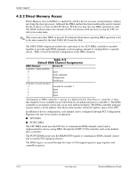
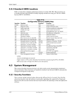
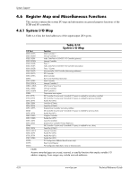
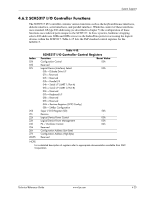
System Support Power-On / Setup Password These systems include a power-on and setup passwords, which may be enabled or disabled (cleared) through a jumper on the system board. The jumper controls a GPIO input to the 82801 ICH8 that is checked during POST. The password is stored in configuration memory (CMOS) and if enabled and then forgotten by the user will require that either the password be cleared (preferable solution and described below) or the entire CMOS be cleared (refer to section 4.4.1). To clear the password, use the following procedure: 1. Turn off the system and disconnect the AC power cord from the outlet and/or system unit. 2. Remove the cover (hood) as described in the appropriate User Guide or Maintainance And Service Reference Guide. Insure that all system board LEDs are off (not illuminated). 3. Locate the password clear jumper (header is colored green and labeled E49 on these systems) and move the jumper from pins 1 and 2 and place on (just) pin 2 (for safekeeping). 4. Replace the cover. 5. Re-connect the AC power cord to the AC outlet and/or system unit. 6. Turn on the system. The POST routine will clear and disable the password. 7. To re-enable the password feature, repeat steps 1-6, replacing the jumper on pins 1 and 2 of header E49. Setup Password The Setup utility may be configured to be always changeable or changeable only by entering a password. Refer to the previous procedure (Power On / Setup Password) for clearing the Setup password. Cable Lock Provision These systems include a chassis cutout (on the rear panel) for the attachment of a cable lock mechanism. I/O Interface Security The serial, parallel, USB, and diskette interfaces may be disabled individually through the Setup utility to guard against unauthorized access to a system. In addition, the ability to write to or boot from a removable media drive (such as the diskette drive) may be enabled through the Setup utility. The disabling of the serial, parallel, and diskette interfaces are a function of the SCH5317 I/O controller. The USB ports are controlled through the 82801. Chassis Security Some systems feature Smart Cover (hood) Sensor and Smart Cover (hood) Lock mechanisms to inhibit unauthorized tampering of the system unit. Smart Cover Sensor Some systems include a plunger switch that, when the cover (hood) is removed, closes and grounds an input of the 82801 component. The battery-backed logic will record this "intrusion" event by setting a specific bit. This bit will remain set (even if the cover is replaced) until the system is powered up and the user completes the boot sequence successfully, at which time the bit will be cleared. Through Setup, the user can set this function to be used by Alert-On-LAN and or one of three levels of support for a "cover removed" condition: Technical Reference Guide www.hp.com 4-21
-
 1
1 -
2
-
3
-
4
-
5
-
6
-
7
-
8
-
9
-
10
-
11
-
12
-
13
-
14
-
15
-
16
-
17
-
18
-
19
-
20
-
21
-
22
-
23
-
24
-
25
-
26
-
27
-
28
-
29
-
30
-
31
-
32
-
33
-
34
-
35
-
36
-
37
-
38
-
39
-
40
-
41
-
42
-
43
-
44
-
45
-
46
-
47
-
48
-
49
-
50
-
51
-
52
-
53
-
54
-
55
-
56
-
57
-
58
-
59
-
60
-
61
-
62
-
63
-
64
-
65
-
66
-
67
-
 68
68 -
 69
69 -
 70
70 -
 71
71 -
 72
72 -
 73
73 -
 74
74 -
 75
75 -
 76
76 -
 77
77 -
 78
78 -
79
-
80
-
81
-
82
-
83
-
84
-
85
-
86
-
87
-
88
-
89
-
90
-
91
-
92
-
93
-
94
-
95
-
96
-
97
-
98
-
99
-
100
-
101
-
102
-
103
-
104
-
105
-
106
-
107
-
108
-
109
-
110
-
111
-
112
-
113
-
114
-
115
-
116
-
117
-
118
-
119
-
120
-
121
-
122
-
123
-
124
-
125
-
126
-
127
-
128
-
129
-
130
-
131
-
132
-
133
-
134
-
135
-
136
-
137
-
138
-
139
-
140
-
141
-
142
-
143
-
144
-
145
-
146
-
147
-
148
-
149
-
150
-
151
-
152
-
153
-
154
-
155
-
156
-
157
-
158
-
159
-
160
-
161
-
162
-
163
-
164
-
165
-
166
-
167
-
168
-
169
-
170
-
171
-
172
-
173
-
174
-
175
-
176
-
177
-
178
-
179
-
180
-
181
-
182
-
183
-
184
-
185
-
186
-
187
-
188
-
189
-
190
-
191
-
192
-
193
-
194
-
195
-
196
 |
 |