HP Dc7700 HP Compaq dx7300 and dc7700 Business PC Technical Reference Guide, 1 - Page 88
Serial Interface Control, Table 5-8.
 |
UPC - 882780715318
View all HP Dc7700 manuals
Add to My Manuals
Save this manual to your list of manuals |
Page 88 highlights
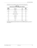
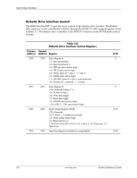
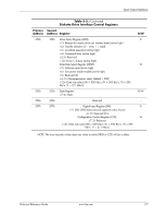
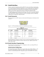
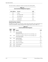
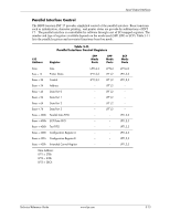
Input/Output Interfaces The serial interface configuration registers are listed in the following table: Table 5-8. Serial Interface Configuration Registers Index Address 30h 60h 61h 70h F0h Function Activate Base Address MSB Base Address LSB Interrupt Select Mode Register R/W R/W R/W R/W R/W R/W Serial Interface Control The BIOS function INT 14 provides basic control of the serial interface. The serial interface can be directly controlled by software through the I/O-mapped registers listed in Table 5-17 Table 5-9. Serial Interface Control Registers COM1 COM2 Addr. Addr. Register 3F8h 2F8h Receive Data Buffer Transmit Data Buffer Baud Rate Divisor Register 0 (when bit 7 of Line Control Reg. Is set) 3F9h 2F9h Baud Rate Divisor Register 1 (when bit 7 of Line Control Reg. Is set) Interrupt Enable Register 3FAh 2FAh Interrupt ID Register FIFO Control Register 3FBh 2FBh Line Control Register 3FCh 2FCh Modem Control Register 3FDh 2FDh Line Status Register 3FEh 2FEh Modem Status R/W R W W W R/W R W R/W R/W R R 5-10 www.hp.com Technical Reference Guide
-
 1
1 -
2
-
3
-
4
-
5
-
6
-
7
-
8
-
9
-
10
-
11
-
12
-
13
-
14
-
15
-
16
-
17
-
18
-
19
-
20
-
21
-
22
-
23
-
24
-
25
-
26
-
27
-
28
-
29
-
30
-
31
-
32
-
33
-
34
-
35
-
36
-
37
-
38
-
39
-
40
-
41
-
42
-
43
-
44
-
45
-
46
-
47
-
48
-
49
-
50
-
51
-
52
-
53
-
54
-
55
-
56
-
57
-
58
-
59
-
60
-
61
-
62
-
63
-
64
-
65
-
66
-
67
-
68
-
69
-
70
-
71
-
72
-
73
-
74
-
75
-
76
-
77
-
78
-
79
-
80
-
81
-
82
-
 83
83 -
 84
84 -
 85
85 -
 86
86 -
 87
87 -
 88
88 -
 89
89 -
 90
90 -
 91
91 -
 92
92 -
 93
93 -
94
-
95
-
96
-
97
-
98
-
99
-
100
-
101
-
102
-
103
-
104
-
105
-
106
-
107
-
108
-
109
-
110
-
111
-
112
-
113
-
114
-
115
-
116
-
117
-
118
-
119
-
120
-
121
-
122
-
123
-
124
-
125
-
126
-
127
-
128
-
129
-
130
-
131
-
132
-
133
-
134
-
135
-
136
-
137
-
138
-
139
-
140
-
141
-
142
-
143
-
144
-
145
-
146
-
147
-
148
-
149
-
150
-
151
-
152
-
153
-
154
-
155
-
156
-
157
-
158
-
159
-
160
-
161
-
162
-
163
-
164
-
165
-
166
-
167
-
168
-
169
-
170
-
171
-
172
-
173
-
174
-
175
-
176
-
177
-
178
-
179
-
180
-
181
-
182
-
183
-
184
-
185
-
186
-
187
-
188
-
189
-
190
-
191
-
192
-
193
-
194
-
195
-
196
 |
 |