HP Dc7700 HP Compaq dx7300 and dc7700 Business PC Technical Reference Guide, 1 - Page 102
USB Programming, USB Configuration
 |
UPC - 882780715318
View all HP Dc7700 manuals
Add to My Manuals
Save this manual to your list of manuals |
Page 102 highlights
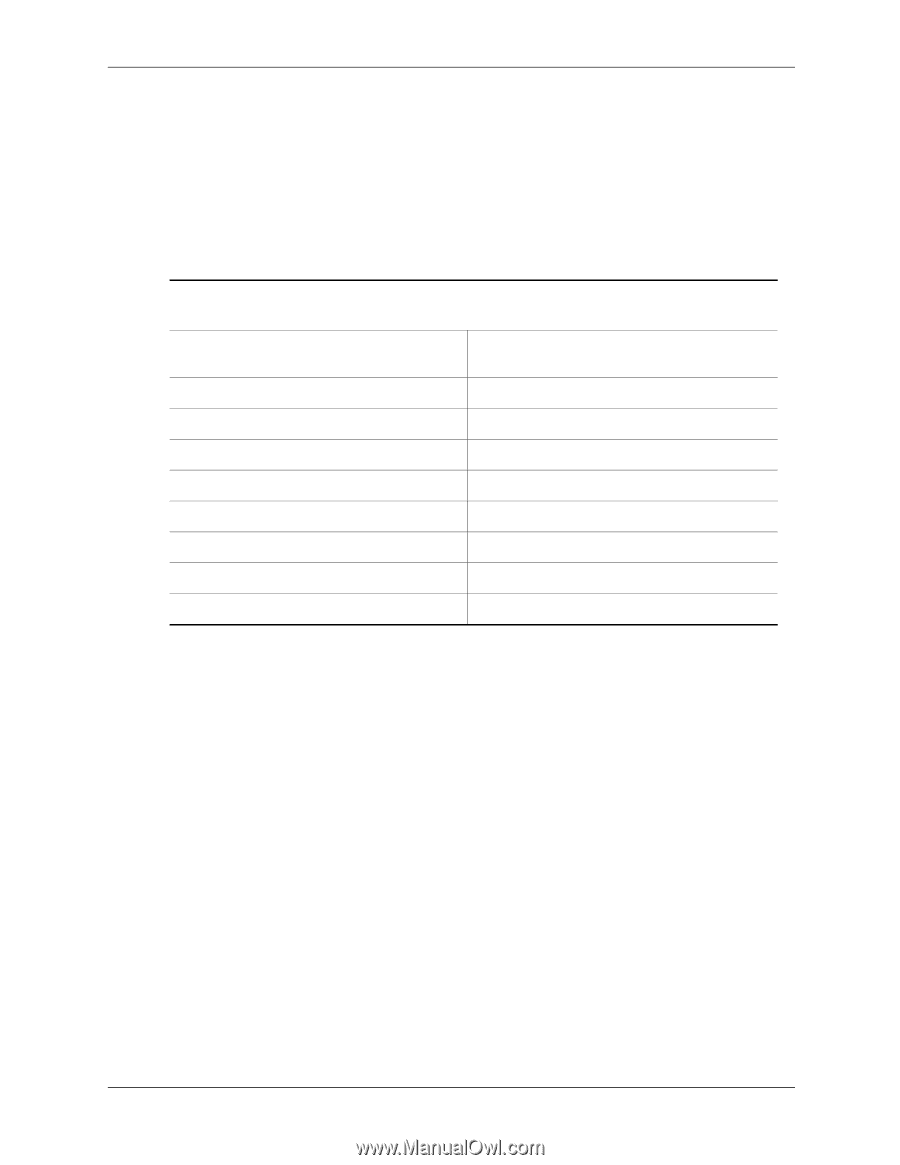
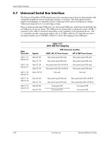
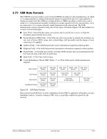
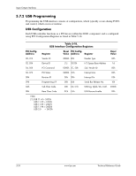
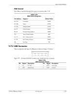
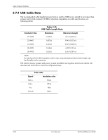
Input/Output Interfaces 5.7.2 USB Programming Programming the USB interface consists of configuration, which typically occurs during POST, and control, which occurs at runtime. USB Configuration Each USB controller functions as a PCI device within the 82801 component and is configured using PCI Configuration Registers as listed in Table 5-18. NOTE: Table 5-18. USB Interface Configuration Registers PCI Config. Address Register Reset PCI Config. Value Address Register Reset Value 00, 01h Vendor ID 8086h 0Eh Header Type 00h 02, 03h Device ID [1] 20-23h I/O Space Base Address 1d 04, 05h PCI Command 0000h 2C, 2Dh Sub. Vender ID 00h 06, 07h PCI Status 0280h 3Ch Interrupt Line 00h 08h Revision ID 00h 3Dh Interrupt Pin 03h 09h Programming I/F 00h 60h Serial Bus Release No. 10h 0Ah Sub Class Code 03h C0, C1h USB Leg. Kybd./Ms. Cntrl. 2000h 0Bh Base Class Code 0Ch C4h USB Resume Enable 00h Note: [1] USB 1.1 #1= 24D2h USB 1.1 #2 = 24D4h USB 1.1 #3 = 24D7h USB 1.1 #4 = 24DDh USB 2.0 = 24DDh 5-24 www.hp.com Technical Reference Guide
-
 1
1 -
2
-
3
-
4
-
5
-
6
-
7
-
8
-
9
-
10
-
11
-
12
-
13
-
14
-
15
-
16
-
17
-
18
-
19
-
20
-
21
-
22
-
23
-
24
-
25
-
26
-
27
-
28
-
29
-
30
-
31
-
32
-
33
-
34
-
35
-
36
-
37
-
38
-
39
-
40
-
41
-
42
-
43
-
44
-
45
-
46
-
47
-
48
-
49
-
50
-
51
-
52
-
53
-
54
-
55
-
56
-
57
-
58
-
59
-
60
-
61
-
62
-
63
-
64
-
65
-
66
-
67
-
68
-
69
-
70
-
71
-
72
-
73
-
74
-
75
-
76
-
77
-
78
-
79
-
80
-
81
-
82
-
83
-
84
-
85
-
86
-
87
-
88
-
89
-
90
-
91
-
92
-
93
-
94
-
95
-
96
-
 97
97 -
 98
98 -
 99
99 -
 100
100 -
 101
101 -
 102
102 -
 103
103 -
 104
104 -
 105
105 -
 106
106 -
 107
107 -
108
-
109
-
110
-
111
-
112
-
113
-
114
-
115
-
116
-
117
-
118
-
119
-
120
-
121
-
122
-
123
-
124
-
125
-
126
-
127
-
128
-
129
-
130
-
131
-
132
-
133
-
134
-
135
-
136
-
137
-
138
-
139
-
140
-
141
-
142
-
143
-
144
-
145
-
146
-
147
-
148
-
149
-
150
-
151
-
152
-
153
-
154
-
155
-
156
-
157
-
158
-
159
-
160
-
161
-
162
-
163
-
164
-
165
-
166
-
167
-
168
-
169
-
170
-
171
-
172
-
173
-
174
-
175
-
176
-
177
-
178
-
179
-
180
-
181
-
182
-
183
-
184
-
185
-
186
-
187
-
188
-
189
-
190
-
191
-
192
-
193
-
194
-
195
-
196
 |
 |