HP Dc7700 HP Compaq dx7300 and dc7700 Business PC Technical Reference Guide, 1 - Page 71
Real-Time Clock and Configuration Memory, 4.4.1 Clearing CMOS
 |
UPC - 882780715318
View all HP Dc7700 manuals
Add to My Manuals
Save this manual to your list of manuals |
Page 71 highlights
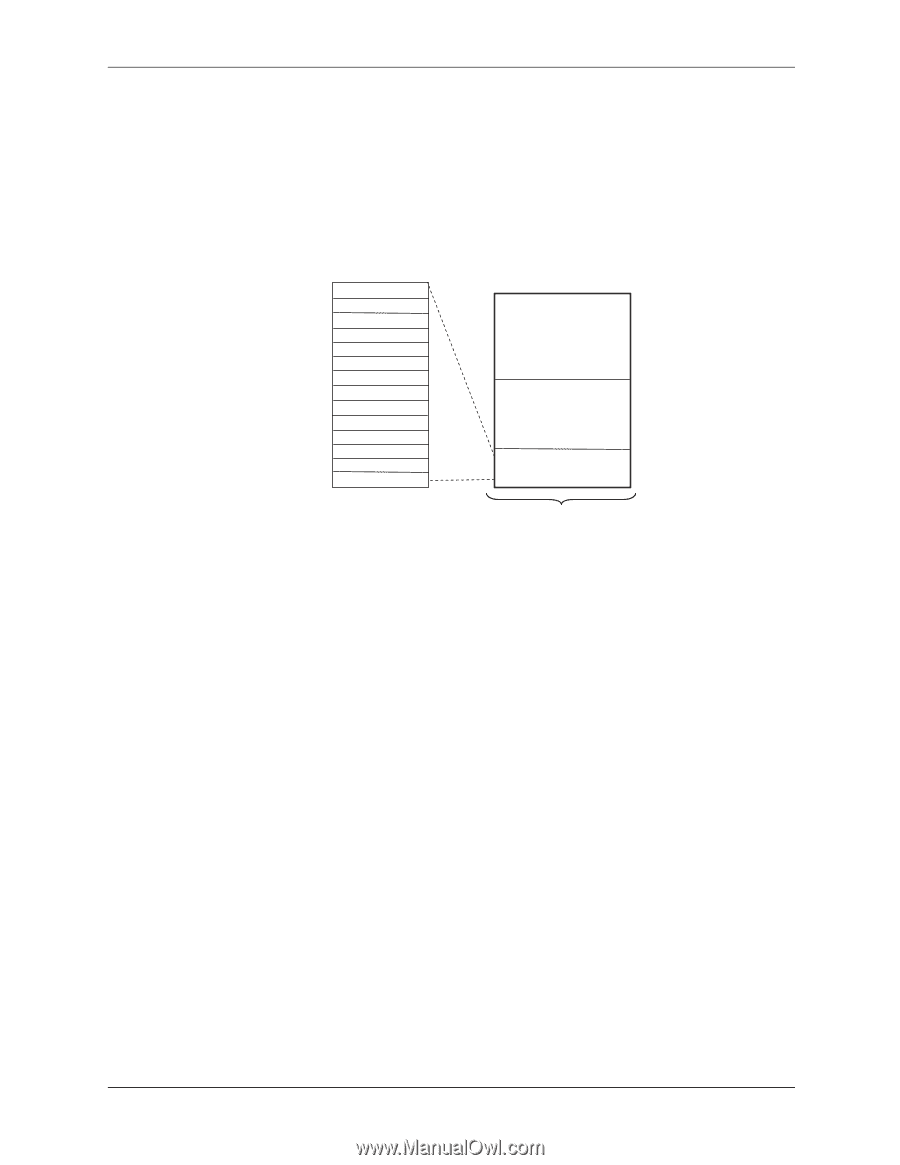
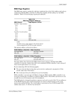
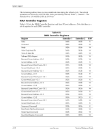
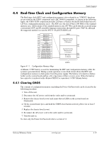
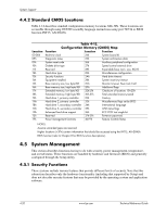
System Support 4.4 Real-Time Clock and Configuration Memory The Real-time clock (RTC) and configuration memory (also referred to as "CMOS") functions are provided by the 82801 component and is MC146818-compatible. As shown in the following figure, the 82801 ICH8 component provides 256 bytes of battery-backed RAM divided into two 128-byte configuration memory areas. The RTC uses the first 14 bytes (00-0Dh) of the standard memory area. All locations of the standard memory area (00-7Fh) can be directly accessed using conventional OUT and IN assembly language instructions through I/O ports 70h/71h, although the suggested method is to use the INT15 AX=E823h BIOS call. 0Dh Register D 0Ch Register C 0Bh Register B 0Ah Register A 09h Year 08h Month 07h Date of Month 06h Day of Week 05h Hours (Alarm) 04h Hours (Timer) 03h Minutes (Alarm) 02h Minutes (Timer) 01h Seconds (Alarm) 00h Seconds (Timer) 82801 FFh Extended Config. Memory Area (128 bytes) 80h 7Fh Standard Config. Memory Area (114 bytes) 0Eh RTC Area 0Dh (14 bytes) 00h CMOS Figure 4 11. Configuration Memory Map A lithium 3-VDC battery is used for maintaining the RTC and configuration memory while the system is powered down. During system operation a wire-Ored circuit allows the RTC and configuration memory to draw power from the power supply. The battery is located in a battery holder on the system board and has a life expectancy of three or more years. When the battery has expired it is replaced with a Renata CR2032 or equivalent 3-VDC lithium battery. 4.4.1 Clearing CMOS The contents of configuration memory (including the Power-On Password) can be cleared by the following procedure: 1. Turn off the unit. 2. Disconnect the AC power cord from the outlet and/or system unit. 3. Remove the chassis hood (cover) and insure that no LEDs on the system board are illuminated. 4. On the system board, press and hold the CMOS clear button (colored yellow) for at least 5 seconds. 5. Replace the chassis hood (cover). 6. Reconnect the AC power cord to the outlet and/or system unit. 7. Turn the unit on. To clear only the Power-On Password refer to section 4.5.1. Technical Reference Guide www.hp.com 4-19
-
 1
1 -
2
-
3
-
4
-
5
-
6
-
7
-
8
-
9
-
10
-
11
-
12
-
13
-
14
-
15
-
16
-
17
-
18
-
19
-
20
-
21
-
22
-
23
-
24
-
25
-
26
-
27
-
28
-
29
-
30
-
31
-
32
-
33
-
34
-
35
-
36
-
37
-
38
-
39
-
40
-
41
-
42
-
43
-
44
-
45
-
46
-
47
-
48
-
49
-
50
-
51
-
52
-
53
-
54
-
55
-
56
-
57
-
58
-
59
-
60
-
61
-
62
-
63
-
64
-
65
-
 66
66 -
 67
67 -
 68
68 -
 69
69 -
 70
70 -
 71
71 -
 72
72 -
 73
73 -
 74
74 -
 75
75 -
 76
76 -
77
-
78
-
79
-
80
-
81
-
82
-
83
-
84
-
85
-
86
-
87
-
88
-
89
-
90
-
91
-
92
-
93
-
94
-
95
-
96
-
97
-
98
-
99
-
100
-
101
-
102
-
103
-
104
-
105
-
106
-
107
-
108
-
109
-
110
-
111
-
112
-
113
-
114
-
115
-
116
-
117
-
118
-
119
-
120
-
121
-
122
-
123
-
124
-
125
-
126
-
127
-
128
-
129
-
130
-
131
-
132
-
133
-
134
-
135
-
136
-
137
-
138
-
139
-
140
-
141
-
142
-
143
-
144
-
145
-
146
-
147
-
148
-
149
-
150
-
151
-
152
-
153
-
154
-
155
-
156
-
157
-
158
-
159
-
160
-
161
-
162
-
163
-
164
-
165
-
166
-
167
-
168
-
169
-
170
-
171
-
172
-
173
-
174
-
175
-
176
-
177
-
178
-
179
-
180
-
181
-
182
-
183
-
184
-
185
-
186
-
187
-
188
-
189
-
190
-
191
-
192
-
193
-
194
-
195
-
196
 |
 |