HP Dc7700 HP Compaq dx7300 and dc7700 Business PC Technical Reference Guide, 1 - Page 69
DMA Registers, Table 4-10., DMA Register Addresses, DMA Channel, Register I/O Port
 |
UPC - 882780715318
View all HP Dc7700 manuals
Add to My Manuals
Save this manual to your list of manuals |
Page 69 highlights
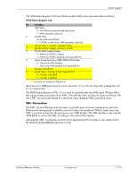
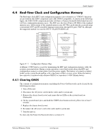
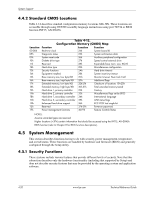
System Support DMA Page Registers The DMA page register contains the eight most significant bits of the 24-bit address and works in conjunction with the DMA controllers to define the complete (24-bit) address for the DMA channels. Table 4-10 lists the page register port addresses. Table 4-10. DMA Page Register Addresses DMA Channel Page Register I/O Port Controller 1 (byte transfers) Ch 0 087h Ch 1 083h Ch 2 081h Ch 3 082h Controller 2 (word transfers) Ch 4 n/a Ch 5 08Bh Ch 6 089h Ch 7 08Ah Refresh 08Fh [see note] NOTE: The DMA memory page register for the refresh channel must be programmed with 00h for proper operation. The memory address is derived as follows: 24-Bit Address-Controller 1 (Byte Transfers) 8-Bit Page Register 8-Bit DMA Controller A23..A16 A15..A00 24-Bit Address-Controller 2 (Word Transfers) 8-Bit Page Register 16-Bit DMA Controller A23..A17 A16..A01, (A00 = 0) Note that address line A16 from the DMA memory page register is disabled when DMA controller 2 is selected. Address line A00 is not connected to DMA controller 2 and is always 0 when word-length transfers are selected. By not connecting A00, the following applies: ■ The size of the the block of data that can be moved or addressed is measured in 16-bits (words) rather than 8-bits (bytes). ■ The words must always be addressed on an even boundary. DMA controller 1 can move up to 64 Kbytes of data per DMA transfer. DMA controller 2 can move up to 64 Kwords (128 Kbytes) of data per DMA transfer. Word DMA operations are only possible between 16-bit memory and 16-bit peripherals. The RAM refresh is designed to perform a memory read cycle on each of the 512 row addresses in the DRAM memory space. Refresh operations are used to refresh memory on the 32-bit memory bus and the ISA bus. The refresh address is provided on lines SA00 through SA08. Address lines LA23..17, SA18,19 are driven low. Technical Reference Guide www.hp.com 4-17
-
 1
1 -
2
-
3
-
4
-
5
-
6
-
7
-
8
-
9
-
10
-
11
-
12
-
13
-
14
-
15
-
16
-
17
-
18
-
19
-
20
-
21
-
22
-
23
-
24
-
25
-
26
-
27
-
28
-
29
-
30
-
31
-
32
-
33
-
34
-
35
-
36
-
37
-
38
-
39
-
40
-
41
-
42
-
43
-
44
-
45
-
46
-
47
-
48
-
49
-
50
-
51
-
52
-
53
-
54
-
55
-
56
-
57
-
58
-
59
-
60
-
61
-
62
-
63
-
 64
64 -
 65
65 -
 66
66 -
 67
67 -
 68
68 -
 69
69 -
 70
70 -
 71
71 -
 72
72 -
 73
73 -
 74
74 -
75
-
76
-
77
-
78
-
79
-
80
-
81
-
82
-
83
-
84
-
85
-
86
-
87
-
88
-
89
-
90
-
91
-
92
-
93
-
94
-
95
-
96
-
97
-
98
-
99
-
100
-
101
-
102
-
103
-
104
-
105
-
106
-
107
-
108
-
109
-
110
-
111
-
112
-
113
-
114
-
115
-
116
-
117
-
118
-
119
-
120
-
121
-
122
-
123
-
124
-
125
-
126
-
127
-
128
-
129
-
130
-
131
-
132
-
133
-
134
-
135
-
136
-
137
-
138
-
139
-
140
-
141
-
142
-
143
-
144
-
145
-
146
-
147
-
148
-
149
-
150
-
151
-
152
-
153
-
154
-
155
-
156
-
157
-
158
-
159
-
160
-
161
-
162
-
163
-
164
-
165
-
166
-
167
-
168
-
169
-
170
-
171
-
172
-
173
-
174
-
175
-
176
-
177
-
178
-
179
-
180
-
181
-
182
-
183
-
184
-
185
-
186
-
187
-
188
-
189
-
190
-
191
-
192
-
193
-
194
-
195
-
196
 |
 |