HP Dc7700 HP Compaq dx7300 and dc7700 Business PC Technical Reference Guide, 1 - Page 60
Option ROM Mapping, 4.2.4 PCI Interrupts, 4.2.5 PCI Power Management Support, The SFF, ST, MT - graphics driver
 |
UPC - 882780715318
View all HP Dc7700 manuals
Add to My Manuals
Save this manual to your list of manuals |
Page 60 highlights
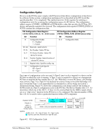
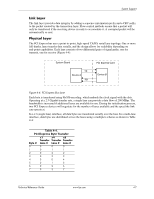
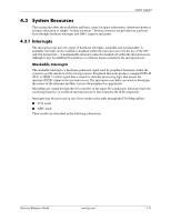
System Support For a PCI Express x16 transfer, a lane will be re-used for the transfer of every17th byte. The mux-demux process provided by the physical layer is transparent to the other layers and to software/drivers. The SFF, ST, MT, and CMT form factors provide two PCI Express slots: a PCI Express x16 (16-lane) slot specifically designed for a graphics controller, and a general purpose PCI Express x1 (1-lane) slot. 4.2.3 Option ROM Mapping During POST, the PCI bus is scanned for devices that contain their own specific firmware in ROM. Such option ROM data, if detected, is loaded into system memory's DOS compatibility area (refer to the system memory map shown in chapter 3). 4.2.4 PCI Interrupts Eight interrupt signals (INTA- thru INTH-) are available for use by PCI devices. These signals may be generated by on-board PCI devices or by devices installed in the PCI slots. For more information on interrupts including PCI interrupt mapping refer to the "System Resources" section 4.3. 4.2.5 PCI Power Management Support This system complies with the PCI Power Management Interface Specification (rev 1.0). The PCI Power Management Enable (PME-) signal is supported by the chipset and allows compliant PCI peripherals to initiate the power management routine. 4-8 www.hp.com Technical Reference Guide
-
 1
1 -
2
-
3
-
4
-
5
-
6
-
7
-
8
-
9
-
10
-
11
-
12
-
13
-
14
-
15
-
16
-
17
-
18
-
19
-
20
-
21
-
22
-
23
-
24
-
25
-
26
-
27
-
28
-
29
-
30
-
31
-
32
-
33
-
34
-
35
-
36
-
37
-
38
-
39
-
40
-
41
-
42
-
43
-
44
-
45
-
46
-
47
-
48
-
49
-
50
-
51
-
52
-
53
-
54
-
 55
55 -
 56
56 -
 57
57 -
 58
58 -
 59
59 -
 60
60 -
 61
61 -
 62
62 -
 63
63 -
 64
64 -
 65
65 -
66
-
67
-
68
-
69
-
70
-
71
-
72
-
73
-
74
-
75
-
76
-
77
-
78
-
79
-
80
-
81
-
82
-
83
-
84
-
85
-
86
-
87
-
88
-
89
-
90
-
91
-
92
-
93
-
94
-
95
-
96
-
97
-
98
-
99
-
100
-
101
-
102
-
103
-
104
-
105
-
106
-
107
-
108
-
109
-
110
-
111
-
112
-
113
-
114
-
115
-
116
-
117
-
118
-
119
-
120
-
121
-
122
-
123
-
124
-
125
-
126
-
127
-
128
-
129
-
130
-
131
-
132
-
133
-
134
-
135
-
136
-
137
-
138
-
139
-
140
-
141
-
142
-
143
-
144
-
145
-
146
-
147
-
148
-
149
-
150
-
151
-
152
-
153
-
154
-
155
-
156
-
157
-
158
-
159
-
160
-
161
-
162
-
163
-
164
-
165
-
166
-
167
-
168
-
169
-
170
-
171
-
172
-
173
-
174
-
175
-
176
-
177
-
178
-
179
-
180
-
181
-
182
-
183
-
184
-
185
-
186
-
187
-
188
-
189
-
190
-
191
-
192
-
193
-
194
-
195
-
196
 |
 |