HP Dc7700 HP Compaq dx7300 and dc7700 Business PC Technical Reference Guide, 1 - Page 107
HD Audio Codec, All functions are controlled through index-addressed registers of the codec. - beep codes
 |
UPC - 882780715318
View all HP Dc7700 manuals
Add to My Manuals
Save this manual to your list of manuals |
Page 107 highlights
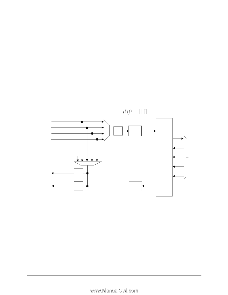
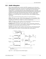
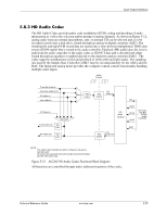
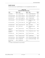
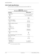
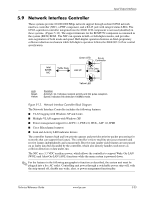
Input/Output Interfaces 5.8.3 HD Audio Codec The HD Audio Codec provides pulse code modulation (PCM) coding and decoding of audio information as well as the selection and/or mixing of analog channels. As shown in Figure 5-12, analog audio from an external microphone, tape, or internal CD can be selected and, if to be recorded (saved) onto a disk drive, routed through an analog-to-digital converter (ADC). The resulting left and right PCM record data are muxed into a time-division-multiplexed (TDM) data stream (SD IN signal) that is routed to the audio controller. Playback (PB) audio takes the reverse path from the audio controller to the audio codec as SD OUT data and is decoded and either routed through an equalizer or applied directly to the digital-to-analog converter (DAC). The codec supports simultaneous record and playback of stereo (left and right) audio. The sampling rate used by the Sample Rate Controllers (SRC) may be set independently for the ADCs and the DAC. The integrated analog mixer provides the computer control-console functionality handling multiple audio inputs. Audio Format Front Mic Audio In Rear Mic Audio In [1] CD Audio In Line Audio In PC Beep In Mux/Gain Line Audio Out PB Gain HP Audio Out PB Gain Mux REC Gain ADC w/SRC L/R Audio In SDI HD Audio Interface RST# BCLK SYNC HD Audio Link Bus to/from Audio Controller DAC w/SRC L/R Audio Out SDO NOTE: The audio codec includes two ADCs. However, only one is typcially used. All audio lines represent both left and right channel information. [1] CMT form factor only. Figure 5-12. ALC262 HD Audio Codec Functional Block Diagram All functions are controlled through index-addressed registers of the codec. Technical Reference Guide www.hp.com 5-29
-
 1
1 -
2
-
3
-
4
-
5
-
6
-
7
-
8
-
9
-
10
-
11
-
12
-
13
-
14
-
15
-
16
-
17
-
18
-
19
-
20
-
21
-
22
-
23
-
24
-
25
-
26
-
27
-
28
-
29
-
30
-
31
-
32
-
33
-
34
-
35
-
36
-
37
-
38
-
39
-
40
-
41
-
42
-
43
-
44
-
45
-
46
-
47
-
48
-
49
-
50
-
51
-
52
-
53
-
54
-
55
-
56
-
57
-
58
-
59
-
60
-
61
-
62
-
63
-
64
-
65
-
66
-
67
-
68
-
69
-
70
-
71
-
72
-
73
-
74
-
75
-
76
-
77
-
78
-
79
-
80
-
81
-
82
-
83
-
84
-
85
-
86
-
87
-
88
-
89
-
90
-
91
-
92
-
93
-
94
-
95
-
96
-
97
-
98
-
99
-
100
-
101
-
 102
102 -
 103
103 -
 104
104 -
 105
105 -
 106
106 -
 107
107 -
 108
108 -
 109
109 -
 110
110 -
 111
111 -
 112
112 -
113
-
114
-
115
-
116
-
117
-
118
-
119
-
120
-
121
-
122
-
123
-
124
-
125
-
126
-
127
-
128
-
129
-
130
-
131
-
132
-
133
-
134
-
135
-
136
-
137
-
138
-
139
-
140
-
141
-
142
-
143
-
144
-
145
-
146
-
147
-
148
-
149
-
150
-
151
-
152
-
153
-
154
-
155
-
156
-
157
-
158
-
159
-
160
-
161
-
162
-
163
-
164
-
165
-
166
-
167
-
168
-
169
-
170
-
171
-
172
-
173
-
174
-
175
-
176
-
177
-
178
-
179
-
180
-
181
-
182
-
183
-
184
-
185
-
186
-
187
-
188
-
189
-
190
-
191
-
192
-
193
-
194
-
195
-
196
 |
 |