HP Dc7700 HP Compaq dx7300 and dc7700 Business PC Technical Reference Guide, 1 - Page 9
Serial Number, 1.5 Notational Conventions, 1.5.1 Values, 1.5.2 Ranges
 |
UPC - 882780715318
View all HP Dc7700 manuals
Add to My Manuals
Save this manual to your list of manuals |
Page 9 highlights
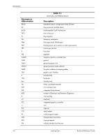
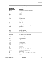
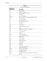
Introduction 1.4 Serial Number The unit's serial number is located on a sticker placed on the exterior cabinet. The serial number is also written into firmware and may be read with HP Diagnostics or Insight Manager utilities. 1.5 Notational Conventions The notational guidelines used in this guide are described in the following subsections. 1.5.1 Values Hexadecimal values are indicated by a numerical or alpha-numerical value followed by the letter "h." Binary values are indicated by a value of ones and zeros followed by the letter "b." Numerical values that have no succeeding letter can be assumed to be decimal unless otherwise stated. 1.5.2 Ranges Ranges or limits for a parameter are shown using the following methods: Example A: Example B: Bits = bits 7, 6, 5, and 4. IRQ3-7, 9 = IRQ signals 3 through 7, and IRQ signal 9 1.5.3 Register Notation and Usage This guide uses standard Intel naming conventions in discussing the microprocessor's (CPU) internal registers. Registers that are accessed through programmable I/O using an indexing scheme are indicated using the following format: 03C5.17h Index port Data port In the example above, register 03C5.17h is accessed by writing the index port value 17h to the index address (03C4h), followed by a write to or a read from port 03C5h. 1.5.4 Bit Notation and Byte Values Bit designations are labeled between brackets (i.e., "bit "). Binary values are shown with the most significant bit (MSb) on the far left, least significant bit (LSb) at the far right. Byte values in hexadecimal are also shown with the MSB on the left, LSB on the right. Technical Reference Guide www.hp.com 1-3
-
 1
1 -
2
-
3
-
 4
4 -
 5
5 -
 6
6 -
 7
7 -
 8
8 -
 9
9 -
 10
10 -
 11
11 -
 12
12 -
 13
13 -
 14
14 -
15
-
16
-
17
-
18
-
19
-
20
-
21
-
22
-
23
-
24
-
25
-
26
-
27
-
28
-
29
-
30
-
31
-
32
-
33
-
34
-
35
-
36
-
37
-
38
-
39
-
40
-
41
-
42
-
43
-
44
-
45
-
46
-
47
-
48
-
49
-
50
-
51
-
52
-
53
-
54
-
55
-
56
-
57
-
58
-
59
-
60
-
61
-
62
-
63
-
64
-
65
-
66
-
67
-
68
-
69
-
70
-
71
-
72
-
73
-
74
-
75
-
76
-
77
-
78
-
79
-
80
-
81
-
82
-
83
-
84
-
85
-
86
-
87
-
88
-
89
-
90
-
91
-
92
-
93
-
94
-
95
-
96
-
97
-
98
-
99
-
100
-
101
-
102
-
103
-
104
-
105
-
106
-
107
-
108
-
109
-
110
-
111
-
112
-
113
-
114
-
115
-
116
-
117
-
118
-
119
-
120
-
121
-
122
-
123
-
124
-
125
-
126
-
127
-
128
-
129
-
130
-
131
-
132
-
133
-
134
-
135
-
136
-
137
-
138
-
139
-
140
-
141
-
142
-
143
-
144
-
145
-
146
-
147
-
148
-
149
-
150
-
151
-
152
-
153
-
154
-
155
-
156
-
157
-
158
-
159
-
160
-
161
-
162
-
163
-
164
-
165
-
166
-
167
-
168
-
169
-
170
-
171
-
172
-
173
-
174
-
175
-
176
-
177
-
178
-
179
-
180
-
181
-
182
-
183
-
184
-
185
-
186
-
187
-
188
-
189
-
190
-
191
-
192
-
193
-
194
-
195
-
196
 |
 |