HP Dc7700 HP Compaq dx7300 and dc7700 Business PC Technical Reference Guide, 1 - Page 92
Parallel Interface Connector, Table 5-12., DB-25 Parallel Connector Pinout
 |
UPC - 882780715318
View all HP Dc7700 manuals
Add to My Manuals
Save this manual to your list of manuals |
Page 92 highlights
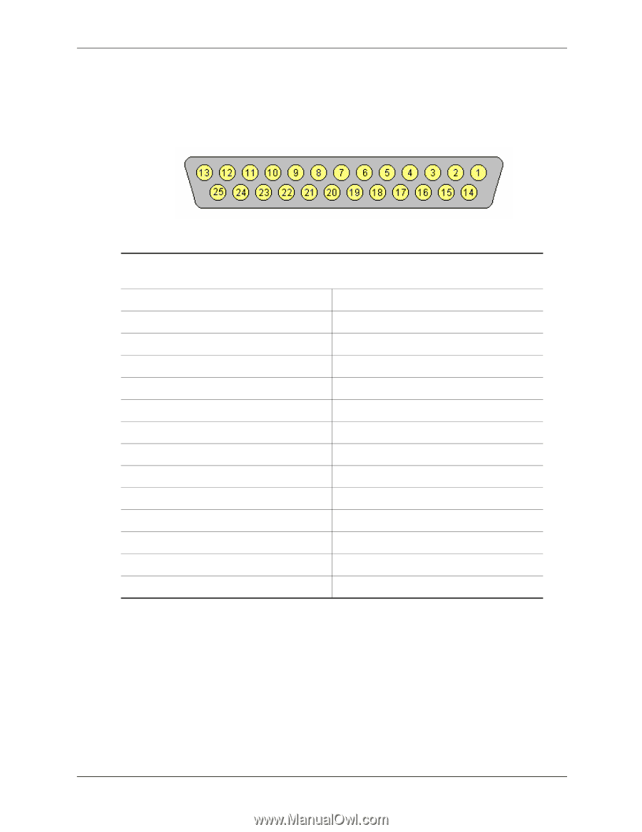
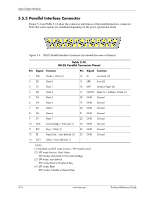
Input/Output Interfaces 5.5.5 Parallel Interface Connector Figure 5-4 and Table 5-12 show the connector and pinout of the parallel interface connector. Note that some signals are redefined depending on the port's operational mode. Figure 5-4. DB-25 Parallel Interface Connector (as viewed from rear of chassis) Table 5-12. DB-25 Parallel Connector Pinout Pin Signal Function Pin Signal Function 1 STB2 D0 Strobe / Write [1] Data 0 14 LF15 ERR- Line Feed [2] Error [3] 3 D1 Data 1 16 INIT- Initialize Paper [4] 4 D2 5 D3 Data 2 Data 3 17 SLCTIN- Select In / Address. Strobe [1] 18 GND Ground 6 D4 Data 4 19 GND Ground 7 D5 8 D6 Data 5 Data 6 20 GND 21 GND Ground Ground 9 D7 10 ACK- Data 7 Acknowledge / Interrupt [1] 22 GND 23 GND Ground Ground 11 BSY Busy / Wait [1] 24 GND Ground 12 PE 13 SLCT Paper End / User defined [1] Select / User defined [1] 25 GND -- -- Ground -- NOTES: [1] Standard and ECP mode function / EPP mode function [2] EPP mode function: Data Strobe ECP modes: Auto Feed or Host Acknowledge [3] EPP mode: user defined ECP modes:Fault or Peripheral Req. [4] EPP mode: Reset ECP modes: Initialize or Reverse Req. 5-14 www.hp.com Technical Reference Guide
-
 1
1 -
2
-
3
-
4
-
5
-
6
-
7
-
8
-
9
-
10
-
11
-
12
-
13
-
14
-
15
-
16
-
17
-
18
-
19
-
20
-
21
-
22
-
23
-
24
-
25
-
26
-
27
-
28
-
29
-
30
-
31
-
32
-
33
-
34
-
35
-
36
-
37
-
38
-
39
-
40
-
41
-
42
-
43
-
44
-
45
-
46
-
47
-
48
-
49
-
50
-
51
-
52
-
53
-
54
-
55
-
56
-
57
-
58
-
59
-
60
-
61
-
62
-
63
-
64
-
65
-
66
-
67
-
68
-
69
-
70
-
71
-
72
-
73
-
74
-
75
-
76
-
77
-
78
-
79
-
80
-
81
-
82
-
83
-
84
-
85
-
86
-
 87
87 -
 88
88 -
 89
89 -
 90
90 -
 91
91 -
 92
92 -
 93
93 -
 94
94 -
 95
95 -
 96
96 -
 97
97 -
98
-
99
-
100
-
101
-
102
-
103
-
104
-
105
-
106
-
107
-
108
-
109
-
110
-
111
-
112
-
113
-
114
-
115
-
116
-
117
-
118
-
119
-
120
-
121
-
122
-
123
-
124
-
125
-
126
-
127
-
128
-
129
-
130
-
131
-
132
-
133
-
134
-
135
-
136
-
137
-
138
-
139
-
140
-
141
-
142
-
143
-
144
-
145
-
146
-
147
-
148
-
149
-
150
-
151
-
152
-
153
-
154
-
155
-
156
-
157
-
158
-
159
-
160
-
161
-
162
-
163
-
164
-
165
-
166
-
167
-
168
-
169
-
170
-
171
-
172
-
173
-
174
-
175
-
176
-
177
-
178
-
179
-
180
-
181
-
182
-
183
-
184
-
185
-
186
-
187
-
188
-
189
-
190
-
191
-
192
-
193
-
194
-
195
-
196
 |
 |