HP Dc7700 HP Compaq dx7300 and dc7700 Business PC Technical Reference Guide, 1 - Page 106
HD Audio Controller, 5.8.2 HD Audio Interface
 |
UPC - 882780715318
View all HP Dc7700 manuals
Add to My Manuals
Save this manual to your list of manuals |
Page 106 highlights
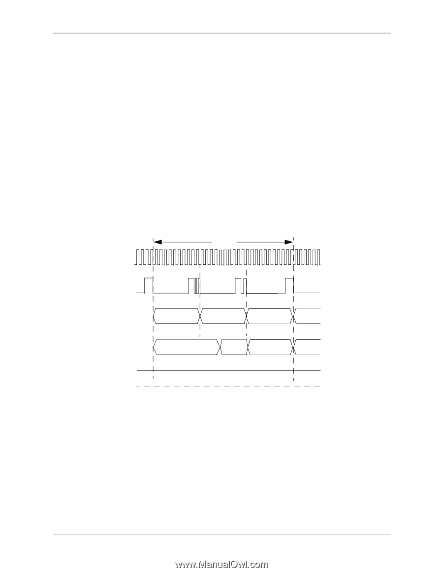
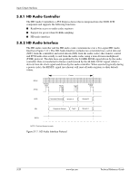
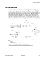
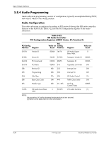
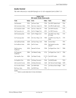
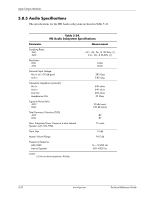
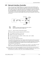
Input/Output Interfaces 5.8.1 HD Audio Controller The HD Audio Controller is a PCI Express device that is integrated into the 82801 ICH component and supports the following functions: ■ Read/write access to audio codec registers ■ Support for greater than 48-KHz sampling ■ HD audio interface 5.8.2 HD Audio Interface The HD audio controller and the HD audio codec communicate over a five-signal HD Audio Interface (Figure 5-11). The HD Audio Interface includes two serial data lines; serial data out (SDO, from the controller) and serial data in (SDI, from the audio codec) that transfer control and PCM audio data serially to and from the audio codec using a time-division multiplexed (TDM) protocol. The data lines are qualified by the 24-MHz BCLK signal driven by the audio controller. Data is transferred in frames synchronized by the 48-KHz SYNC signal, which is derived from the clock signal and driven by the audio controller. When asserted (typically during a power cycle), the RESET- signal (not shown) will reset all audio registers to their default values. Frame BCLK SYNC Frame Start Tag A Tag B Frame Start SDO Command Stream Stream A Stream B SDI Response Stream Tag C Stream C RST# NOTE: Clock not drawn to scale. Figure 5-11. HD Audio Interface Protocol 5-28 www.hp.com Technical Reference Guide
-
 1
1 -
2
-
3
-
4
-
5
-
6
-
7
-
8
-
9
-
10
-
11
-
12
-
13
-
14
-
15
-
16
-
17
-
18
-
19
-
20
-
21
-
22
-
23
-
24
-
25
-
26
-
27
-
28
-
29
-
30
-
31
-
32
-
33
-
34
-
35
-
36
-
37
-
38
-
39
-
40
-
41
-
42
-
43
-
44
-
45
-
46
-
47
-
48
-
49
-
50
-
51
-
52
-
53
-
54
-
55
-
56
-
57
-
58
-
59
-
60
-
61
-
62
-
63
-
64
-
65
-
66
-
67
-
68
-
69
-
70
-
71
-
72
-
73
-
74
-
75
-
76
-
77
-
78
-
79
-
80
-
81
-
82
-
83
-
84
-
85
-
86
-
87
-
88
-
89
-
90
-
91
-
92
-
93
-
94
-
95
-
96
-
97
-
98
-
99
-
100
-
 101
101 -
 102
102 -
 103
103 -
 104
104 -
 105
105 -
 106
106 -
 107
107 -
 108
108 -
 109
109 -
 110
110 -
 111
111 -
112
-
113
-
114
-
115
-
116
-
117
-
118
-
119
-
120
-
121
-
122
-
123
-
124
-
125
-
126
-
127
-
128
-
129
-
130
-
131
-
132
-
133
-
134
-
135
-
136
-
137
-
138
-
139
-
140
-
141
-
142
-
143
-
144
-
145
-
146
-
147
-
148
-
149
-
150
-
151
-
152
-
153
-
154
-
155
-
156
-
157
-
158
-
159
-
160
-
161
-
162
-
163
-
164
-
165
-
166
-
167
-
168
-
169
-
170
-
171
-
172
-
173
-
174
-
175
-
176
-
177
-
178
-
179
-
180
-
181
-
182
-
183
-
184
-
185
-
186
-
187
-
188
-
189
-
190
-
191
-
192
-
193
-
194
-
195
-
196
 |
 |