HP Dc7700 HP Compaq dx7300 and dc7700 Business PC Technical Reference Guide, 1 - Page 68
Direct Memory Access, Table 4-9., Default DMA Channel Assignments
 |
UPC - 882780715318
View all HP Dc7700 manuals
Add to My Manuals
Save this manual to your list of manuals |
Page 68 highlights
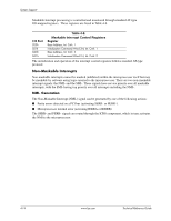
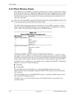
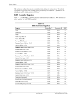
System Support 4.3.2 Direct Memory Access Direct Memory Access (DMA) is a method by which a device accesses system memory without involving the microprocessor. Although the DMA method has been traditionally used to transfer blocks of data to or from an ISA I/O device, PCI devices may also use DMA operation as well. The DMA method reduces the amount of CPU interactions with memory, freeing the CPU for other processing tasks. ✎ This section describes DMA in general. For detailed information regarding DMA operation, refer to the data manual for the Intel 82801 I/O Controller Hub. The 82801 ICH8 component includes the equivalent of two 8237 DMA controllers cascaded together to provide eight DMA channels, each (excepting channel 4) configurable to a specific device. Table 4-9 lists the default configuration of the DMA channels. Table 4-9. Default DMA Channel Assignments DMA Channel Device ID Controller 1 (byte transfers) 0 Spare 1 Audio subsystem 2 Diskette drive 3 Parallel port Controller 2 (word transfers) 4 Cascade for controller 1 5 Spare 6 Spare 7 Spare All channels in DMA controller 1 operate at a higher priority than those in controller 2. Note that channel 4 is not available for use other than its cascading function for controller 1. The DMA controller 2 can transfer words only on an even address boundary. The DMA controller and page register define a 24-bit address that allows data transfers within the address space of the CPU. In addition to device configuration, each channel can be configured (through PCI Configuration Registers) for one of two modes of operation: ■ LPC DMA ■ PC/PCI DMA The LPC DMA mode uses the LPC bus to communicate DMA channel control and is implemented for devices using DMA through the SCH5317 I/O controller such as the diskette drive controller. The PC/PCI DMA mode uses the REQ#/GNT# signals to communicate DMA channel control and is used by PCI expansion devices. The DMA logic is accessed through two types of I/O mapped registers; page registers and controller registers. 4-16 www.hp.com Technical Reference Guide
-
 1
1 -
2
-
3
-
4
-
5
-
6
-
7
-
8
-
9
-
10
-
11
-
12
-
13
-
14
-
15
-
16
-
17
-
18
-
19
-
20
-
21
-
22
-
23
-
24
-
25
-
26
-
27
-
28
-
29
-
30
-
31
-
32
-
33
-
34
-
35
-
36
-
37
-
38
-
39
-
40
-
41
-
42
-
43
-
44
-
45
-
46
-
47
-
48
-
49
-
50
-
51
-
52
-
53
-
54
-
55
-
56
-
57
-
58
-
59
-
60
-
61
-
62
-
 63
63 -
 64
64 -
 65
65 -
 66
66 -
 67
67 -
 68
68 -
 69
69 -
 70
70 -
 71
71 -
 72
72 -
 73
73 -
74
-
75
-
76
-
77
-
78
-
79
-
80
-
81
-
82
-
83
-
84
-
85
-
86
-
87
-
88
-
89
-
90
-
91
-
92
-
93
-
94
-
95
-
96
-
97
-
98
-
99
-
100
-
101
-
102
-
103
-
104
-
105
-
106
-
107
-
108
-
109
-
110
-
111
-
112
-
113
-
114
-
115
-
116
-
117
-
118
-
119
-
120
-
121
-
122
-
123
-
124
-
125
-
126
-
127
-
128
-
129
-
130
-
131
-
132
-
133
-
134
-
135
-
136
-
137
-
138
-
139
-
140
-
141
-
142
-
143
-
144
-
145
-
146
-
147
-
148
-
149
-
150
-
151
-
152
-
153
-
154
-
155
-
156
-
157
-
158
-
159
-
160
-
161
-
162
-
163
-
164
-
165
-
166
-
167
-
168
-
169
-
170
-
171
-
172
-
173
-
174
-
175
-
176
-
177
-
178
-
179
-
180
-
181
-
182
-
183
-
184
-
185
-
186
-
187
-
188
-
189
-
190
-
191
-
192
-
193
-
194
-
195
-
196
 |
 |