HP Dc7700 HP Compaq dx7300 and dc7700 Business PC Technical Reference Guide, 1 - Page 103
USB Connector, USB Control
 |
UPC - 882780715318
View all HP Dc7700 manuals
Add to My Manuals
Save this manual to your list of manuals |
Page 103 highlights
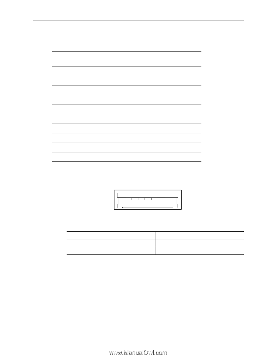
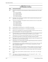
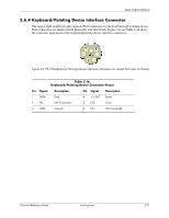
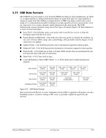
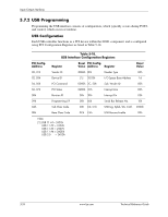
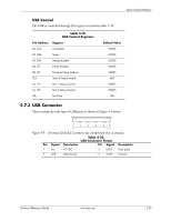
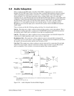
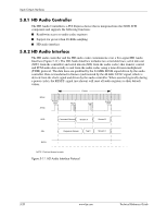
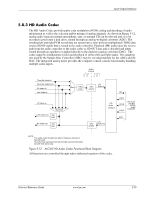
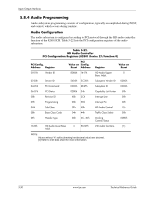
Input/Output Interfaces USB Control The USB is controlled through I/O registers as listed in table 5-19. Table 5-19. USB Control Registers I/O Address Register 00, 01h Command 02, 03h Status 04, 05h Interupt Enable 06, 07 Frame Number 08, 0B Frame List Base Address 0Ch Start of Frame Modify 10, 11h Port 1 Status/Control 12, 13h Port 2 Status/Control 18h Test Data Default Value 0000h 0000h 0000h 0000h 0000h 40h 0080h 0080h 00h 5.7.3 USB Connector These systems provide type-A USB ports as shown in Figure 5-9 below. 1 2 3 4 Figure 5-9. Universal Serial Bus Connector (as viewed from rear of chassis) Table 5-20. USB Connector Pinout Pin Signal Description Pin Signal Description 1 Vcc +5 VDC 3 USB+ Data (plus) 2 USB- Data (minus) 4 GND Ground Technical Reference Guide www.hp.com 5-25
-
 1
1 -
2
-
3
-
4
-
5
-
6
-
7
-
8
-
9
-
10
-
11
-
12
-
13
-
14
-
15
-
16
-
17
-
18
-
19
-
20
-
21
-
22
-
23
-
24
-
25
-
26
-
27
-
28
-
29
-
30
-
31
-
32
-
33
-
34
-
35
-
36
-
37
-
38
-
39
-
40
-
41
-
42
-
43
-
44
-
45
-
46
-
47
-
48
-
49
-
50
-
51
-
52
-
53
-
54
-
55
-
56
-
57
-
58
-
59
-
60
-
61
-
62
-
63
-
64
-
65
-
66
-
67
-
68
-
69
-
70
-
71
-
72
-
73
-
74
-
75
-
76
-
77
-
78
-
79
-
80
-
81
-
82
-
83
-
84
-
85
-
86
-
87
-
88
-
89
-
90
-
91
-
92
-
93
-
94
-
95
-
96
-
97
-
 98
98 -
 99
99 -
 100
100 -
 101
101 -
 102
102 -
 103
103 -
 104
104 -
 105
105 -
 106
106 -
 107
107 -
 108
108 -
109
-
110
-
111
-
112
-
113
-
114
-
115
-
116
-
117
-
118
-
119
-
120
-
121
-
122
-
123
-
124
-
125
-
126
-
127
-
128
-
129
-
130
-
131
-
132
-
133
-
134
-
135
-
136
-
137
-
138
-
139
-
140
-
141
-
142
-
143
-
144
-
145
-
146
-
147
-
148
-
149
-
150
-
151
-
152
-
153
-
154
-
155
-
156
-
157
-
158
-
159
-
160
-
161
-
162
-
163
-
164
-
165
-
166
-
167
-
168
-
169
-
170
-
171
-
172
-
173
-
174
-
175
-
176
-
177
-
178
-
179
-
180
-
181
-
182
-
183
-
184
-
185
-
186
-
187
-
188
-
189
-
190
-
191
-
192
-
193
-
194
-
195
-
196
 |
 |