HP Dc7700 HP Compaq dx7300 and dc7700 Business PC Technical Reference Guide, 1 - Page 87
Serial Interface, 5.4.1 Serial Connector, 5.4.2 Serial Interface Programming
 |
UPC - 882780715318
View all HP Dc7700 manuals
Add to My Manuals
Save this manual to your list of manuals |
Page 87 highlights
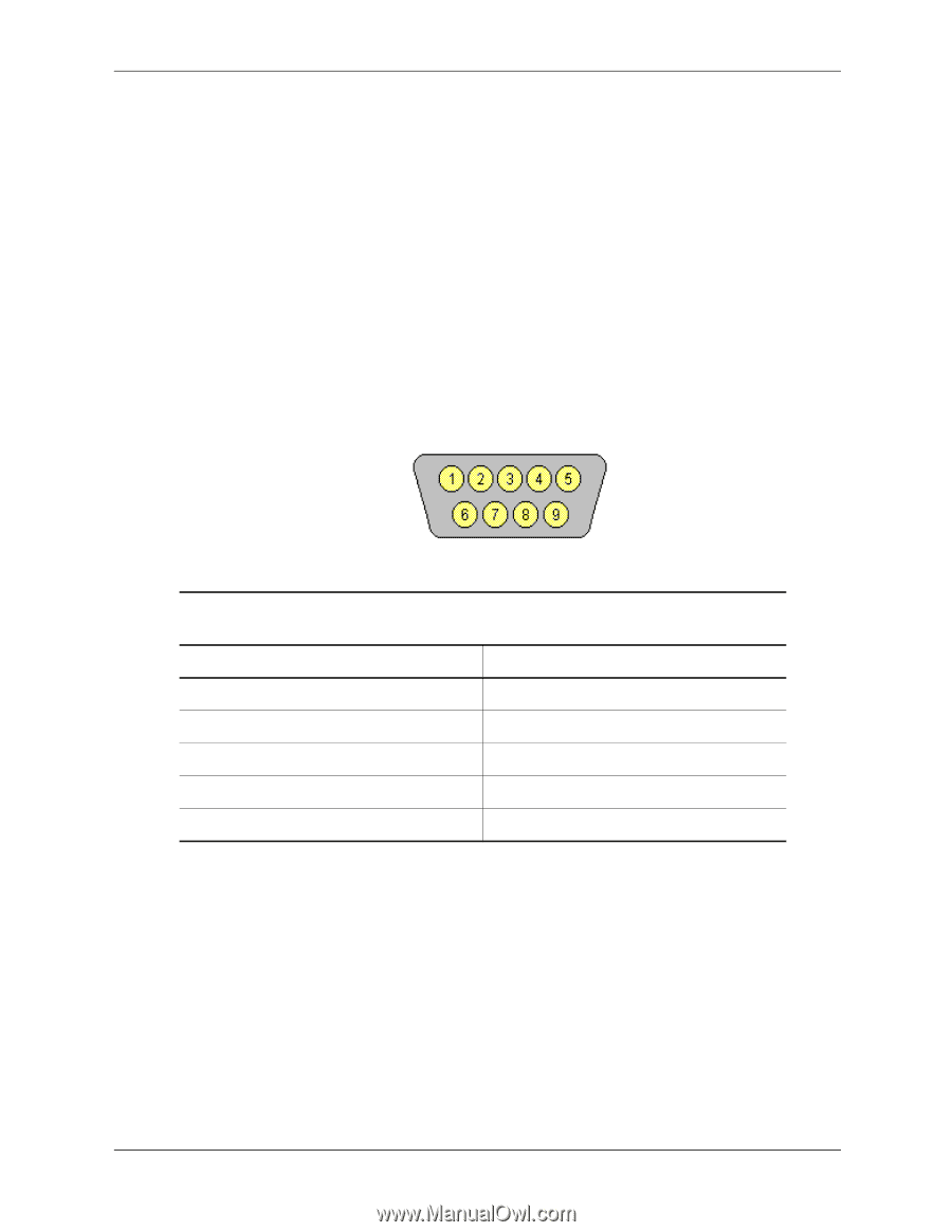
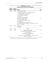
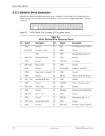
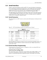
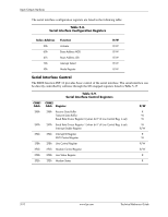
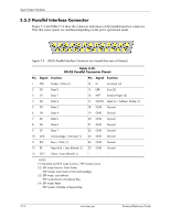
Input/Output Interfaces 5.4 Serial Interface Systems covered in this guide may include one RS-232-C type serial interface to transmit and receive asynchronous serial data with external devices. Some systems may allow the installation of a second serial interface through an adapter that consists of a PCI bracket and a cable that attaches to header P52 on the system board. The serial interface function is provided by the SCH5317 I/O controller component that includes two NS16C550-compatible UARTs. The UART supports the standard baud rates up through 115200, and also special high speed rates of 239400 and 460800 baud. The baud rate of the UART is typically set to match the capability of the connected device. While most baud rates may be set at runtime, baud rates 230400 and 460800 must be set during the configuration phase. 5.4.1 Serial Connector The serial interface uses a DB-9 connector as shown in the following figure with the pinout listed in Table 5-7. Figure 5-3. DB-9 Serial Interface Connector (as viewed from rear of chassis) Pin Signal 1 CD 2 RX Data 3 TX Data 4 DTR 5 GND Table 5-7. DB-9 Serial Connector Pinout Description Pin Signal Description Carrier Detect 6 DSR Data Set Ready Receive Data 7 RTS Request To Send Transmit Data 8 CTS Clear To Send Data Terminal Ready 9 RI Ring Indicator Ground -- -- -- The standard RS-232-C limitation of 50 feet (or less) of cable between the DTE (computer) and DCE (modem) should be followed to minimize transmission errors. Higher baud rates may require shorter cables. 5.4.2 Serial Interface Programming Programming the serial interfaces consists of configuration, which occurs during POST, and control, which occurs during runtime. Serial Interface Configuration The serial interface must be configured for a specific address range (COM1, COM2, etc.) and also must be activated before it can be used. Address selection and activation of the serial interface are affected through the PnP configuration registers of the SCH5317 I/O controller. Technical Reference Guide www.hp.com 5-9
-
 1
1 -
2
-
3
-
4
-
5
-
6
-
7
-
8
-
9
-
10
-
11
-
12
-
13
-
14
-
15
-
16
-
17
-
18
-
19
-
20
-
21
-
22
-
23
-
24
-
25
-
26
-
27
-
28
-
29
-
30
-
31
-
32
-
33
-
34
-
35
-
36
-
37
-
38
-
39
-
40
-
41
-
42
-
43
-
44
-
45
-
46
-
47
-
48
-
49
-
50
-
51
-
52
-
53
-
54
-
55
-
56
-
57
-
58
-
59
-
60
-
61
-
62
-
63
-
64
-
65
-
66
-
67
-
68
-
69
-
70
-
71
-
72
-
73
-
74
-
75
-
76
-
77
-
78
-
79
-
80
-
81
-
 82
82 -
 83
83 -
 84
84 -
 85
85 -
 86
86 -
 87
87 -
 88
88 -
 89
89 -
 90
90 -
 91
91 -
 92
92 -
93
-
94
-
95
-
96
-
97
-
98
-
99
-
100
-
101
-
102
-
103
-
104
-
105
-
106
-
107
-
108
-
109
-
110
-
111
-
112
-
113
-
114
-
115
-
116
-
117
-
118
-
119
-
120
-
121
-
122
-
123
-
124
-
125
-
126
-
127
-
128
-
129
-
130
-
131
-
132
-
133
-
134
-
135
-
136
-
137
-
138
-
139
-
140
-
141
-
142
-
143
-
144
-
145
-
146
-
147
-
148
-
149
-
150
-
151
-
152
-
153
-
154
-
155
-
156
-
157
-
158
-
159
-
160
-
161
-
162
-
163
-
164
-
165
-
166
-
167
-
168
-
169
-
170
-
171
-
172
-
173
-
174
-
175
-
176
-
177
-
178
-
179
-
180
-
181
-
182
-
183
-
184
-
185
-
186
-
187
-
188
-
189
-
190
-
191
-
192
-
193
-
194
-
195
-
196
 |
 |