HP Dc7700 HP Compaq dx7300 and dc7700 Business PC Technical Reference Guide, 1 - Page 82
Diskette Drive Interface, 5.3.1 Diskette Drive Programming
 |
UPC - 882780715318
View all HP Dc7700 manuals
Add to My Manuals
Save this manual to your list of manuals |
Page 82 highlights
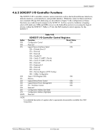
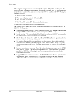
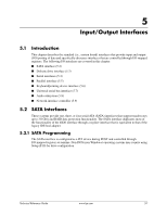
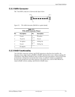
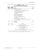
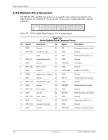
Input/Output Interfaces 5.3 Diskette Drive Interface The MT and CMT form factors support a diskette drive through a standard 34-pin diskette drive connector. Selected models come standard with a 3.5-inch 1.44-MB diskette drive installed as drive A. The diskette drive interface function is integrated into the SCH5317 super I/O component. The internal logic of the I/O controller is software-compatible with standard 82077-type logic. The diskette drive controller has three operational phases in the following order: ■ Command phase-The controller receives the command from the system. ■ Execution phase-The controller carries out the command. ■ Results phase-Status and results data is read back from the controller to the system. The Command phase consists of several bytes written in series from the CPU to the data register (3F5h/375h). The first byte identifies the command and the remaining bytes define the parameters of the command. The Main Status register (3F4h/374h) provides data flow control for the diskette drive controller and must be polled between each byte transfer during the Command phase. The Execution phase starts as soon as the last byte of the Command phase is received. An Execution phase may involve the transfer of data to and from the diskette drive, a mechnical control function of the drive, or an operation that remains internal to the diskette drive controller. Data transfers (writes or reads) with the diskette drive controller are by DMA, using the DRQ2 and DACK2- signals for control. The Results phase consists of the CPU reading a series of status bytes (from the data register (3F5h/375h)) that indicate the results of the command. Note that some commands do not have a Result phase, in which case the Execution phase can be followed by a Command phase. During periods of inactivity, the diskette drive controller is in a non-operation mode known as the Idle phase. 5.3.1 Diskette Drive Programming Programming the diskette drive interface consists of configuration, which occurs typically during POST, and control, which occurs at runtime. Diskette Drive Interface Configuration The diskette drive controller must be configured for a specific address and also must be enabled before it can be used. Address selection and enabling of the diskette drive interface are affected by firmware through the PnP configuration registers of the SCH5317 I/O controller during POST. The configuration registers are accessed through I/O registers 2Eh (index) and 2Fh (data) after the configuration phase has been activated by writing 55h to I/O port 2Eh. The diskette drive I/F is initiated by firmware selecting logical device 0 of the SCH5317 using the following sequence: 1. Write 07h to I/O register 2Eh. 2. Write 00h to I/O register 2Fh (this selects the diskette drive I/F). 3. Write 30h to I/O register 2Eh. 4. Write 01h to I/O register 2Fh (this activates the interface). Writing AAh to 2Eh deactivates the configuration phase. 5-4 www.hp.com Technical Reference Guide
-
 1
1 -
2
-
3
-
4
-
5
-
6
-
7
-
8
-
9
-
10
-
11
-
12
-
13
-
14
-
15
-
16
-
17
-
18
-
19
-
20
-
21
-
22
-
23
-
24
-
25
-
26
-
27
-
28
-
29
-
30
-
31
-
32
-
33
-
34
-
35
-
36
-
37
-
38
-
39
-
40
-
41
-
42
-
43
-
44
-
45
-
46
-
47
-
48
-
49
-
50
-
51
-
52
-
53
-
54
-
55
-
56
-
57
-
58
-
59
-
60
-
61
-
62
-
63
-
64
-
65
-
66
-
67
-
68
-
69
-
70
-
71
-
72
-
73
-
74
-
75
-
76
-
 77
77 -
 78
78 -
 79
79 -
 80
80 -
 81
81 -
 82
82 -
 83
83 -
 84
84 -
 85
85 -
 86
86 -
 87
87 -
88
-
89
-
90
-
91
-
92
-
93
-
94
-
95
-
96
-
97
-
98
-
99
-
100
-
101
-
102
-
103
-
104
-
105
-
106
-
107
-
108
-
109
-
110
-
111
-
112
-
113
-
114
-
115
-
116
-
117
-
118
-
119
-
120
-
121
-
122
-
123
-
124
-
125
-
126
-
127
-
128
-
129
-
130
-
131
-
132
-
133
-
134
-
135
-
136
-
137
-
138
-
139
-
140
-
141
-
142
-
143
-
144
-
145
-
146
-
147
-
148
-
149
-
150
-
151
-
152
-
153
-
154
-
155
-
156
-
157
-
158
-
159
-
160
-
161
-
162
-
163
-
164
-
165
-
166
-
167
-
168
-
169
-
170
-
171
-
172
-
173
-
174
-
175
-
176
-
177
-
178
-
179
-
180
-
181
-
182
-
183
-
184
-
185
-
186
-
187
-
188
-
189
-
190
-
191
-
192
-
193
-
194
-
195
-
196
 |
 |