HP Dc7700 HP Compaq dx7300 and dc7700 Business PC Technical Reference Guide, 1 - Page 74
Power Management, Level 0 - bios update firmware
 |
UPC - 882780715318
View all HP Dc7700 manuals
Add to My Manuals
Save this manual to your list of manuals |
Page 74 highlights
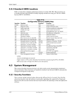
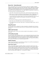
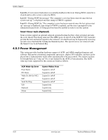
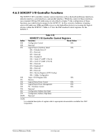
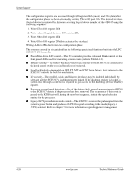
System Support Level 0-Cover removal indication is essentially disabled at this level. During POST, status bit is cleared and no other action is taken by BIOS. Level 1-During POST the message "The computer's cover has been removed since the last system start up" is displayed and time stamp in CMOS is updated. Level 2-During POST the "The computer's cover has been removed since the last system start up" message is displayed, time stamp in CMOS is updated, and the user is prompted for the administrator password. (A Setup password must be enabled in order to see this option). Smart Cover Lock (Optional) Some systems support an optional solenoid-operated locking bar that, when activated, prevents the cover (hood) from being removed. The GPIO ports 44 and 45 of the SCH5317 I/O controller provide the lock and unlock signals to the solenoid. A locked hood may be bypassed by removing special screws that hold the locking mechanism in place. The special screws are removed with the Smart Cover Lock Failsafe Key. 4.5.2 Power Management This system provides baseline hardware support of ACPI- and APM-compliant firmware and software. Key power-consuming components (processor, chipset, I/O controller, and fan) can be placed into a reduced power mode either automatically or by user control. The system can then be brought back up ("wake-up") by events defined by the ACPI 2.0 specification. The ACPI wake-up events supported by this system are listed as follows: ACPI Wake-Up Event Power Button RTC Alarm Wake On LAN (w/NIC) PME Serial Port Ring USB Keyboard Mouse System Wakes From Suspend or soft-off Suspend or soft-off Suspend or soft-off Suspend or soft-off Suspend or soft-off Suspend only Suspend only Suspend only 4-22 www.hp.com Technical Reference Guide
-
 1
1 -
2
-
3
-
4
-
5
-
6
-
7
-
8
-
9
-
10
-
11
-
12
-
13
-
14
-
15
-
16
-
17
-
18
-
19
-
20
-
21
-
22
-
23
-
24
-
25
-
26
-
27
-
28
-
29
-
30
-
31
-
32
-
33
-
34
-
35
-
36
-
37
-
38
-
39
-
40
-
41
-
42
-
43
-
44
-
45
-
46
-
47
-
48
-
49
-
50
-
51
-
52
-
53
-
54
-
55
-
56
-
57
-
58
-
59
-
60
-
61
-
62
-
63
-
64
-
65
-
66
-
67
-
68
-
 69
69 -
 70
70 -
 71
71 -
 72
72 -
 73
73 -
 74
74 -
 75
75 -
 76
76 -
 77
77 -
 78
78 -
 79
79 -
80
-
81
-
82
-
83
-
84
-
85
-
86
-
87
-
88
-
89
-
90
-
91
-
92
-
93
-
94
-
95
-
96
-
97
-
98
-
99
-
100
-
101
-
102
-
103
-
104
-
105
-
106
-
107
-
108
-
109
-
110
-
111
-
112
-
113
-
114
-
115
-
116
-
117
-
118
-
119
-
120
-
121
-
122
-
123
-
124
-
125
-
126
-
127
-
128
-
129
-
130
-
131
-
132
-
133
-
134
-
135
-
136
-
137
-
138
-
139
-
140
-
141
-
142
-
143
-
144
-
145
-
146
-
147
-
148
-
149
-
150
-
151
-
152
-
153
-
154
-
155
-
156
-
157
-
158
-
159
-
160
-
161
-
162
-
163
-
164
-
165
-
166
-
167
-
168
-
169
-
170
-
171
-
172
-
173
-
174
-
175
-
176
-
177
-
178
-
179
-
180
-
181
-
182
-
183
-
184
-
185
-
186
-
187
-
188
-
189
-
190
-
191
-
192
-
193
-
194
-
195
-
196
 |
 |