HP Dc7700 HP Compaq dx7300 and dc7700 Business PC Technical Reference Guide, 1 - Page 86
Diskette Drive Connector, Table 5-6., Pin Diskette Drive Connector Pinout
 |
UPC - 882780715318
View all HP Dc7700 manuals
Add to My Manuals
Save this manual to your list of manuals |
Page 86 highlights
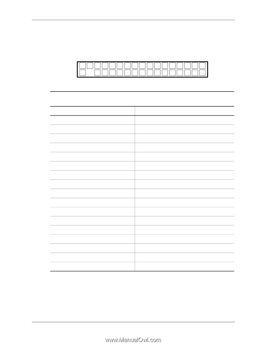
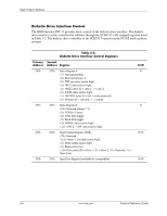
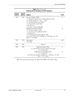
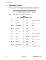
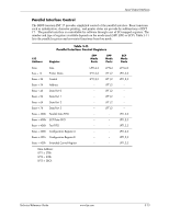
Input/Output Interfaces 5.3.2 Diskette Drive Connector The SFF, ST, MT, and CMT form factors use a standard 34-pin connector for diskette drives (refer to Figure 5-2 and Table 5-6 for the pinout). Drive power is supplied through a separate connector. 2 4 6 8 10 12 14 16 18 20 22 24 26 28 30 32 34 1 5 7 9 11 13 15 17 19 21 23 25 27 29 31 33 Figure 5-2. 34-Pin Diskette Drive Connector (P10 on system board). Pin Signal 1 GND 2 LOW DEN- 3 --- 4 MEDIA ID- 5 GND 6 DRV 4 SEL- 7 GND 8 INDEX- 9 GND 10 MTR 1 ON- 11 GND 12 DRV 2 SEL- 13 GND 14 DRV 1 SEL- 15 GND 16 MTR 2 ON- 17 GND Table 5-6. 34-Pin Diskette Drive Connector Pinout Description Pin Signal Description Ground 18 DIR- Drive head direction control Low density select 19 GND Ground (KEY) 20 STEP- Drive head track step cntrl. Media identification 21 GND Ground Ground 22 WR DATA- Write data Drive 4 select 23 GND Ground Ground 24 WR ENABLE- Enable for WR DATA- Media index is detected 25 GND Ground Ground 26 TRK 00- Heads at track 00 indicator Activates drive motor 27 GND Ground Ground 28 WR PRTK- Media write protect status Drive 2 select 29 GND Ground Ground 30 RD DATA- Data and clock read off disk Drive 1 select 31 GND Ground Ground 32 SIDE SEL- Head select (side 0 or 1) Activates drive motor 33 GND Ground Ground 34 DSK CHG- Drive door opened indicator 5-8 www.hp.com Technical Reference Guide
-
 1
1 -
2
-
3
-
4
-
5
-
6
-
7
-
8
-
9
-
10
-
11
-
12
-
13
-
14
-
15
-
16
-
17
-
18
-
19
-
20
-
21
-
22
-
23
-
24
-
25
-
26
-
27
-
28
-
29
-
30
-
31
-
32
-
33
-
34
-
35
-
36
-
37
-
38
-
39
-
40
-
41
-
42
-
43
-
44
-
45
-
46
-
47
-
48
-
49
-
50
-
51
-
52
-
53
-
54
-
55
-
56
-
57
-
58
-
59
-
60
-
61
-
62
-
63
-
64
-
65
-
66
-
67
-
68
-
69
-
70
-
71
-
72
-
73
-
74
-
75
-
76
-
77
-
78
-
79
-
80
-
 81
81 -
 82
82 -
 83
83 -
 84
84 -
 85
85 -
 86
86 -
 87
87 -
 88
88 -
 89
89 -
 90
90 -
 91
91 -
92
-
93
-
94
-
95
-
96
-
97
-
98
-
99
-
100
-
101
-
102
-
103
-
104
-
105
-
106
-
107
-
108
-
109
-
110
-
111
-
112
-
113
-
114
-
115
-
116
-
117
-
118
-
119
-
120
-
121
-
122
-
123
-
124
-
125
-
126
-
127
-
128
-
129
-
130
-
131
-
132
-
133
-
134
-
135
-
136
-
137
-
138
-
139
-
140
-
141
-
142
-
143
-
144
-
145
-
146
-
147
-
148
-
149
-
150
-
151
-
152
-
153
-
154
-
155
-
156
-
157
-
158
-
159
-
160
-
161
-
162
-
163
-
164
-
165
-
166
-
167
-
168
-
169
-
170
-
171
-
172
-
173
-
174
-
175
-
176
-
177
-
178
-
179
-
180
-
181
-
182
-
183
-
184
-
185
-
186
-
187
-
188
-
189
-
190
-
191
-
192
-
193
-
194
-
195
-
196
 |
 |