HP Dc7700 HP Compaq dx7300 and dc7700 Business PC Technical Reference Guide, 1 - Page 75
System Status, 4.5.4 Thermal Sensing and Cooling - video problems
 |
UPC - 882780715318
View all HP Dc7700 manuals
Add to My Manuals
Save this manual to your list of manuals |
Page 75 highlights
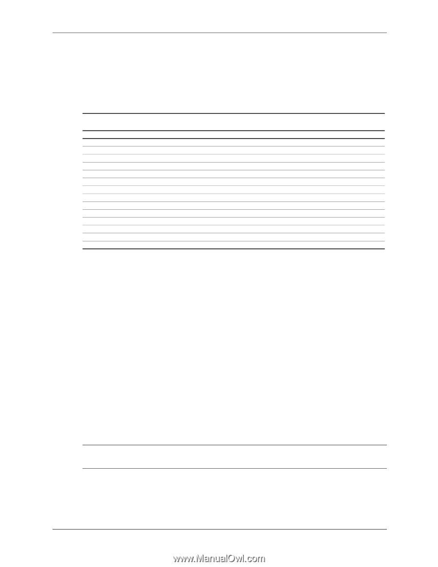
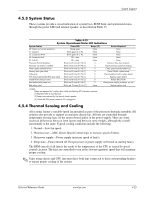
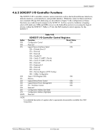
System Support 4.5.3 System Status These systems provide a visual indication of system boot, ROM flash, and operational status through the power LED and internal speaker, as described in Table 13. d . Table 4-13. System Operational Status LED Indications System Status PowerLED Beeps [2] Action Required S0: System on (normal operation) Steady green None None S1: Suspend Blinks green @ .5 Hz None None S3: Suspend to RAM Blinks green @ .5 Hz None None S4: Suspend to disk Off - clear None None S5: Soft off Off - clear None None Processor thermal shutdown Blinks red 2 times @ I Hz [1] 2 Check air flow, fans, heatsink Processor not seated / installed Blinks red 3 times @ I Hz [1] 3 Check processor presence/seating Power supply overload failure Blinks red 4 times @ I Hz [1] 4 Check system board problem [3], Memory error (pre-video) Blinks red 5 times @ I Hz [1] 5 Check DIMMs, system board Video error Blinks red 6 times @ I Hz [1] 6 Check graphics card or system board PCA failure detected by BIOS (pre-video) Blinks red 7 times @ I Hz [1] 7 Replace system board Invalid ROM checksum error Blinks red 8 times @ I Hz [1] 8 Reflash BIOS ROM Boot failure (after power on) Blinks red 9 times @ I Hz [1] 9 Check power supply, processor, sys. bd Bad option card Blinks red 10 times @ I Hz [1] None Replace option card NOTES: Beeps are repeated for 5 cycles, after which only blinking LED indication continues. [1] Repeated after 2 second pause. [2] Beeps are produced by the internal chassis speaker. [3] Check that CPU power connector P3 is plugged in. 4.5.4 Thermal Sensing and Cooling All systems feature a variable-speed fan mounted as part of the processor heatsink assembly. All systems also provide or support an auxiliary chassis fan. All fans are controlled through temperature sensing logic on the system board and/or in the power supply. There are some electrical differences between form factors and between some models, although the overall functionally is the same. Typical cooling conditions include the following: 1. Normal-Low fan speed. 2. Hot processor-ASIC directs Speed Control logic to increase speed of fan(s). 3. Hot power supply-Power supply increases speed of fan(s). 4. Sleep state-Fan(s) turned off. Hot processor or power supply will result in starting fan(s). The RPM (speed) of all fans is the result of the temperature of the CPU as sensed by speed control circuitry. The fans are controlled to run at the slowest (quietest) speed that will maintain proper cooling. ✎ Units using chassis and CPU fans must have both fans connected to their corresponding headers to ensure proper cooling of the system. Technical Reference Guide www.hp.com 4-23
-
 1
1 -
2
-
3
-
4
-
5
-
6
-
7
-
8
-
9
-
10
-
11
-
12
-
13
-
14
-
15
-
16
-
17
-
18
-
19
-
20
-
21
-
22
-
23
-
24
-
25
-
26
-
27
-
28
-
29
-
30
-
31
-
32
-
33
-
34
-
35
-
36
-
37
-
38
-
39
-
40
-
41
-
42
-
43
-
44
-
45
-
46
-
47
-
48
-
49
-
50
-
51
-
52
-
53
-
54
-
55
-
56
-
57
-
58
-
59
-
60
-
61
-
62
-
63
-
64
-
65
-
66
-
67
-
68
-
69
-
 70
70 -
 71
71 -
 72
72 -
 73
73 -
 74
74 -
 75
75 -
 76
76 -
 77
77 -
 78
78 -
 79
79 -
 80
80 -
81
-
82
-
83
-
84
-
85
-
86
-
87
-
88
-
89
-
90
-
91
-
92
-
93
-
94
-
95
-
96
-
97
-
98
-
99
-
100
-
101
-
102
-
103
-
104
-
105
-
106
-
107
-
108
-
109
-
110
-
111
-
112
-
113
-
114
-
115
-
116
-
117
-
118
-
119
-
120
-
121
-
122
-
123
-
124
-
125
-
126
-
127
-
128
-
129
-
130
-
131
-
132
-
133
-
134
-
135
-
136
-
137
-
138
-
139
-
140
-
141
-
142
-
143
-
144
-
145
-
146
-
147
-
148
-
149
-
150
-
151
-
152
-
153
-
154
-
155
-
156
-
157
-
158
-
159
-
160
-
161
-
162
-
163
-
164
-
165
-
166
-
167
-
168
-
169
-
170
-
171
-
172
-
173
-
174
-
175
-
176
-
177
-
178
-
179
-
180
-
181
-
182
-
183
-
184
-
185
-
186
-
187
-
188
-
189
-
190
-
191
-
192
-
193
-
194
-
195
-
196
 |
 |