HP Dc7700 HP Compaq dx7300 and dc7700 Business PC Technical Reference Guide, 1 - Page 89
Parallel Interface, 5.5.1 Standard Parallel Port Mode
 |
UPC - 882780715318
View all HP Dc7700 manuals
Add to My Manuals
Save this manual to your list of manuals |
Page 89 highlights
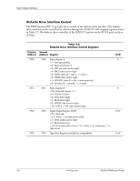
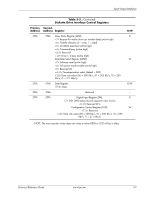
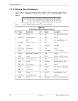
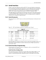
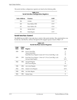
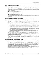
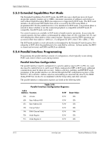
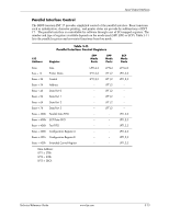
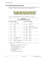
Input/Output Interfaces 5.5 Parallel Interface Systems covered in this guide may include a parallel interface for connection to a peripheral device with a compatible interface, the most common being a printer. The parallel interface function is integrated into the SCH5317 I/O controller component and provides bi-directional 8-bit parallel data transfers with a peripheral device. The parallel interface supports three main modes of operation: ■ Standard Parallel Port (SPP) mode ■ Enhanced Parallel Port (EPP) mode ■ Extended Capabilities Port (ECP) mode These three modes (and their submodes) provide complete support as specified for an IEEE 1284 parallel port. 5.5.1 Standard Parallel Port Mode The Standard Parallel Port (SPP) mode uses software-based protocol and includes two sub-modes of operation, compatible and extended, both of which can provide data transfers up to 150 KB/s. In the compatible mode, CPU write data is simply presented on the eight data lines. A CPU read of the parallel port yields the last data byte that was written. The following steps define the standard procedure for communicating with a printing device: 1. The system checks the Printer Status register. If the Busy, Paper Out, or Printer Fault signals are indicated as being active, the system either waits for a status change or generates an error message. 2. The system sends a byte of data to the Printer Data register, then pulses the printer STROBE signal (through the Printer Control register) for at least 500 ns. 3. The system then monitors the Printer Status register for acknowledgment of the data byte before sending the next byte. In extended mode, a direction control bit (CTR 37Ah, bit ) controls the latching of output data while allowing a CPU read to fetch data present on the data lines, thereby providing bi-directional parallel transfers to occur. The SPP mode uses three registers for operation: the Data register (DTR), the Status register (STR) and the Control register (CTR). Address decoding in SPP mode includes address lines A0 and A1. 5.5.2 Enhanced Parallel Port Mode In Enhanced Parallel Port (EPP) mode, increased data transfers are possible (up to 2 MB/s) due to a hardware protocol that provides automatic address and strobe generation. EPP revisions 1.7 and 1.9 are both supported. For the parallel interface to be initialized for EPP mode, a negotiation phase is entered to detect whether or not the connected peripheral is compatible with EPP mode. If compatible, then EPP mode can be used. In EPP mode, system timing is closely coupled to EPP timing. A watchdog timer is used to prevent system lockup. Five additional registers are available in EPP mode to handle 16- and 32-bit CPU accesses with the parallel interface. Address decoding includes address lines A0, A1, and A2. Technical Reference Guide www.hp.com 5-11
-
 1
1 -
2
-
3
-
4
-
5
-
6
-
7
-
8
-
9
-
10
-
11
-
12
-
13
-
14
-
15
-
16
-
17
-
18
-
19
-
20
-
21
-
22
-
23
-
24
-
25
-
26
-
27
-
28
-
29
-
30
-
31
-
32
-
33
-
34
-
35
-
36
-
37
-
38
-
39
-
40
-
41
-
42
-
43
-
44
-
45
-
46
-
47
-
48
-
49
-
50
-
51
-
52
-
53
-
54
-
55
-
56
-
57
-
58
-
59
-
60
-
61
-
62
-
63
-
64
-
65
-
66
-
67
-
68
-
69
-
70
-
71
-
72
-
73
-
74
-
75
-
76
-
77
-
78
-
79
-
80
-
81
-
82
-
83
-
 84
84 -
 85
85 -
 86
86 -
 87
87 -
 88
88 -
 89
89 -
 90
90 -
 91
91 -
 92
92 -
 93
93 -
 94
94 -
95
-
96
-
97
-
98
-
99
-
100
-
101
-
102
-
103
-
104
-
105
-
106
-
107
-
108
-
109
-
110
-
111
-
112
-
113
-
114
-
115
-
116
-
117
-
118
-
119
-
120
-
121
-
122
-
123
-
124
-
125
-
126
-
127
-
128
-
129
-
130
-
131
-
132
-
133
-
134
-
135
-
136
-
137
-
138
-
139
-
140
-
141
-
142
-
143
-
144
-
145
-
146
-
147
-
148
-
149
-
150
-
151
-
152
-
153
-
154
-
155
-
156
-
157
-
158
-
159
-
160
-
161
-
162
-
163
-
164
-
165
-
166
-
167
-
168
-
169
-
170
-
171
-
172
-
173
-
174
-
175
-
176
-
177
-
178
-
179
-
180
-
181
-
182
-
183
-
184
-
185
-
186
-
187
-
188
-
189
-
190
-
191
-
192
-
193
-
194
-
195
-
196
 |
 |