HP Dc7700 HP Compaq dx7300 and dc7700 Business PC Technical Reference Guide, 1 - Page 84
Diskette Drive Interface Control, Table 5-5. - bios reset
 |
UPC - 882780715318
View all HP Dc7700 manuals
Add to My Manuals
Save this manual to your list of manuals |
Page 84 highlights
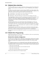
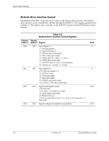
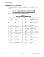
Input/Output Interfaces Diskette Drive Interface Control The BIOS function INT 13 provides basic control of the diskette drive interface. The diskette drive interface can be controlled by software through the SCH5317's I/O-mapped registers listed in Table 5-5. The diskette drive controller of the SCH5317 operates in the PC/AT mode in these systems. Table 5-5. Diskette Drive Interface Control Registers Primary Second. Address Address Register 3F0h 370h Status Register A: Interrupt pending Reserved (always 1) STEP pin status (active high) TRK 0 status (active high) HDSEL status (0 = side 0, 1 = side 1) INDEX status (active high) WR PRTK status (0 = disk is write protected) Direction (0 = outward, 1 = inward) 3F1h 371h Status Register B: Reserved (always 1's) DOR bit 0 status Write data toggle Read data toggle WGATE status (active high) MTR 2, 1 ON- status (active high) 3F2h 372h Digital Output Register (DOR): Reserved Motor 1, 0 enable (active high) DMA enable (active high) Reset (active low) Drive select (00 = Drive 1, 01 = Drive 2, 10 = Reserved, 11 = Tape drive) 3F3h 373h Tape Drive Register (available for compatibility) R/W R R R/W R/W 5-6 www.hp.com Technical Reference Guide
-
 1
1 -
2
-
3
-
4
-
5
-
6
-
7
-
8
-
9
-
10
-
11
-
12
-
13
-
14
-
15
-
16
-
17
-
18
-
19
-
20
-
21
-
22
-
23
-
24
-
25
-
26
-
27
-
28
-
29
-
30
-
31
-
32
-
33
-
34
-
35
-
36
-
37
-
38
-
39
-
40
-
41
-
42
-
43
-
44
-
45
-
46
-
47
-
48
-
49
-
50
-
51
-
52
-
53
-
54
-
55
-
56
-
57
-
58
-
59
-
60
-
61
-
62
-
63
-
64
-
65
-
66
-
67
-
68
-
69
-
70
-
71
-
72
-
73
-
74
-
75
-
76
-
77
-
78
-
 79
79 -
 80
80 -
 81
81 -
 82
82 -
 83
83 -
 84
84 -
 85
85 -
 86
86 -
 87
87 -
 88
88 -
 89
89 -
90
-
91
-
92
-
93
-
94
-
95
-
96
-
97
-
98
-
99
-
100
-
101
-
102
-
103
-
104
-
105
-
106
-
107
-
108
-
109
-
110
-
111
-
112
-
113
-
114
-
115
-
116
-
117
-
118
-
119
-
120
-
121
-
122
-
123
-
124
-
125
-
126
-
127
-
128
-
129
-
130
-
131
-
132
-
133
-
134
-
135
-
136
-
137
-
138
-
139
-
140
-
141
-
142
-
143
-
144
-
145
-
146
-
147
-
148
-
149
-
150
-
151
-
152
-
153
-
154
-
155
-
156
-
157
-
158
-
159
-
160
-
161
-
162
-
163
-
164
-
165
-
166
-
167
-
168
-
169
-
170
-
171
-
172
-
173
-
174
-
175
-
176
-
177
-
178
-
179
-
180
-
181
-
182
-
183
-
184
-
185
-
186
-
187
-
188
-
189
-
190
-
191
-
192
-
193
-
194
-
195
-
196
 |
 |