HP Dc7700 HP Compaq dx7300 and dc7700 Business PC Technical Reference Guide, 1 - Page 56
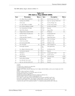
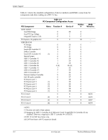
Table 4-1 shows the standard configuration of device numbers and IDSEL connections
 |
UPC - 882780715318
View all HP Dc7700 manuals
Add to My Manuals
Save this manual to your list of manuals |
Page 56 highlights
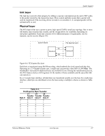
System Support Table 4-1 shows the standard configuration of device numbers and IDSEL connections for components and slots residing on a PCI 2.3 bus. Table 4-1 PCI Component Configuration Access PCI Component Q965 GMCH: Host/DMI Bridge Host/PCI Expr. Bridge Integrated Graphics Cntlr. PCI Express x16 graphics slot 82801EB ICH8 PCI Bridge LPC Bridge Serial ATA Controller #1 SMBus Controller Serial ATA Controller #2 Thermal System USB 1.1 Controller #1 USB 1.1 Controller #2 USB 1.1 Controller #3 USB 1.1 Controller #4 USB 1.1 Controller #5 USB 2.0 Controller #1 USB 2.0 Controller #2 Network Interface Controller Intel HD audio controller PCI Express port 1 PCI Express port 2 PCI Express port 3 PCI Express port 4 PCI Express port 5 PCI Express port 6 PCI 2.3 slot 1 PCI 2.3 slot 2 PCI 2.3 slot 3 PCI 2.3 slot 4 Notes Function # 0 0 0 0 0 0 2 3 [1] 5 6 0 1 2 3 [2] 1 7 7 0 0 0 [1] 1 [1] 2 [1] 3 [1] 4 [1] 5 0 [3] 0 [4] 0 [4] 0 Device # 28 1 2 0 30 31 31 31 31 31 29 29 29 29 [2] 26 29 26 25 27 28 28 28 28 28 28 4 9 10 11 PCI Bus # 0 0 0 32 0 0 0 0 0 0 0 0 0 0 0 0 0 0 0 0 0 0 0 0 0 8 8 8 8 IDSEL Wired to: ---- AD20 AD25 AD27 AD29 NOTES: [1] Function not used in these systems. [2] Mapping for USB 1.1 Controller #4 if USB ports 9 and 10 and USB 2.0 Controller #2 are disabled. Otherwise, mapping for USB 1.1 controller #4 is F0:D25. [3] SFF, ST, & CMT form factors only. [4] CMT form factor with PCI expansion board. 4-4 www.hp.com Technical Reference Guide
-
 1
1 -
2
-
3
-
4
-
5
-
6
-
7
-
8
-
9
-
10
-
11
-
12
-
13
-
14
-
15
-
16
-
17
-
18
-
19
-
20
-
21
-
22
-
23
-
24
-
25
-
26
-
27
-
28
-
29
-
30
-
31
-
32
-
33
-
34
-
35
-
36
-
37
-
38
-
39
-
40
-
41
-
42
-
43
-
44
-
45
-
46
-
47
-
48
-
49
-
50
-
 51
51 -
 52
52 -
 53
53 -
 54
54 -
 55
55 -
 56
56 -
 57
57 -
 58
58 -
 59
59 -
 60
60 -
 61
61 -
62
-
63
-
64
-
65
-
66
-
67
-
68
-
69
-
70
-
71
-
72
-
73
-
74
-
75
-
76
-
77
-
78
-
79
-
80
-
81
-
82
-
83
-
84
-
85
-
86
-
87
-
88
-
89
-
90
-
91
-
92
-
93
-
94
-
95
-
96
-
97
-
98
-
99
-
100
-
101
-
102
-
103
-
104
-
105
-
106
-
107
-
108
-
109
-
110
-
111
-
112
-
113
-
114
-
115
-
116
-
117
-
118
-
119
-
120
-
121
-
122
-
123
-
124
-
125
-
126
-
127
-
128
-
129
-
130
-
131
-
132
-
133
-
134
-
135
-
136
-
137
-
138
-
139
-
140
-
141
-
142
-
143
-
144
-
145
-
146
-
147
-
148
-
149
-
150
-
151
-
152
-
153
-
154
-
155
-
156
-
157
-
158
-
159
-
160
-
161
-
162
-
163
-
164
-
165
-
166
-
167
-
168
-
169
-
170
-
171
-
172
-
173
-
174
-
175
-
176
-
177
-
178
-
179
-
180
-
181
-
182
-
183
-
184
-
185
-
186
-
187
-
188
-
189
-
190
-
191
-
192
-
193
-
194
-
195
-
196
 |
 |