HP Dc7700 HP Compaq dx7300 and dc7700 Business PC Technical Reference Guide, 1 - Page 58
PCI Express Bus Operation, Software/Driver Layer, Transaction Protocol Layer - sff drivers
 |
UPC - 882780715318
View all HP Dc7700 manuals
Add to My Manuals
Save this manual to your list of manuals |
Page 58 highlights
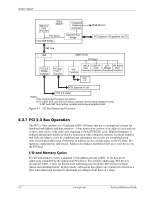
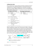
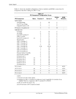
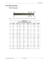
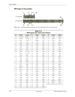
System Support Table 4-3. PCI Bus Mastering Devices Device REQ/GNT Line PCI Connector Slot 1 REQ0/GNT0 PCI Connector Slot 2 REQ1/GNT1 PCI Connector Slot 3 REQ2/GNT2 PCI Connector Slot 4 REQ3/GNT3 Note [1] [2] [2] NOTE: [1] SFF, ST, MT, and CMT form factors only. [2] CMT form factor with PCI expansion board PCI bus arbitration is based on a round-robin scheme that complies with the fairness algorithm specified by the PCI specification. The bus parking policy allows for the current PCI bus owner (excepting the PCI/ISA bridge) to maintain ownership of the bus as long as no request is asserted by another agent. Note that most CPU-to-DRAM accesses can occur concurrently with PCI traffic, therefore reducing the need for the Host/PCI bridge to compete for PCI bus ownership. 4.2.2 PCI Express Bus Operation The PCI Express bus is a high-performace extension of the legacy PCI bus specification. The PCI Express bus uses the following layers: ■ Software/driver layer ■ Transaction protocol layer ■ Link layer ■ Physical layer Software/Driver Layer The PCI Express bus maintains software compatibility with PCI 2.3 and earlier versions so that there is no impact on existing operating systems and drivers. During system intialization, the PCI Express bus uses the same methods of device discovery and resource allocation that legacy PCI-based operating systems and drivers are designed to use. The use of PCI configuration space and the programmability of I/O devices are also used in the same way as for legacy PCI buses (although PCI Express operation uses more configuration space). The software/driver layer provides read and write requests to the transaction layer for handling a data transfer. Transaction Protocol Layer The transaction protocol layer processes read and write requests from the software/driver layer and generates request packets for the link layer. Each packet includes an identifier allowing any required responcse packets to be directed to the originator. PCI Express protocol supports the three legacy PCI address spaces (memory, I/O, configuration) as well as a new message space. The message space allows in-band processing of interrupts through use of the Message Signal Interrupt (MSI) introduced with the PCI 2.2 specification. The MSI method eliminates the need for hard-wired sideband signals by incorporating those functions into packets. 4-6 www.hp.com Technical Reference Guide
-
 1
1 -
2
-
3
-
4
-
5
-
6
-
7
-
8
-
9
-
10
-
11
-
12
-
13
-
14
-
15
-
16
-
17
-
18
-
19
-
20
-
21
-
22
-
23
-
24
-
25
-
26
-
27
-
28
-
29
-
30
-
31
-
32
-
33
-
34
-
35
-
36
-
37
-
38
-
39
-
40
-
41
-
42
-
43
-
44
-
45
-
46
-
47
-
48
-
49
-
50
-
51
-
52
-
 53
53 -
 54
54 -
 55
55 -
 56
56 -
 57
57 -
 58
58 -
 59
59 -
 60
60 -
 61
61 -
 62
62 -
 63
63 -
64
-
65
-
66
-
67
-
68
-
69
-
70
-
71
-
72
-
73
-
74
-
75
-
76
-
77
-
78
-
79
-
80
-
81
-
82
-
83
-
84
-
85
-
86
-
87
-
88
-
89
-
90
-
91
-
92
-
93
-
94
-
95
-
96
-
97
-
98
-
99
-
100
-
101
-
102
-
103
-
104
-
105
-
106
-
107
-
108
-
109
-
110
-
111
-
112
-
113
-
114
-
115
-
116
-
117
-
118
-
119
-
120
-
121
-
122
-
123
-
124
-
125
-
126
-
127
-
128
-
129
-
130
-
131
-
132
-
133
-
134
-
135
-
136
-
137
-
138
-
139
-
140
-
141
-
142
-
143
-
144
-
145
-
146
-
147
-
148
-
149
-
150
-
151
-
152
-
153
-
154
-
155
-
156
-
157
-
158
-
159
-
160
-
161
-
162
-
163
-
164
-
165
-
166
-
167
-
168
-
169
-
170
-
171
-
172
-
173
-
174
-
175
-
176
-
177
-
178
-
179
-
180
-
181
-
182
-
183
-
184
-
185
-
186
-
187
-
188
-
189
-
190
-
191
-
192
-
193
-
194
-
195
-
196
 |
 |
