HP Dc7700 HP Compaq dx7300 and dc7700 Business PC Technical Reference Guide, 1 - Page 80
SATA Configuration Registers, SATA Bus Master Control Registers, Table 5-1., Device 31/Function 2 - virtualization
 |
UPC - 882780715318
View all HP Dc7700 manuals
Add to My Manuals
Save this manual to your list of manuals |
Page 80 highlights
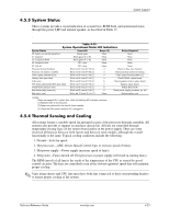
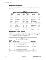
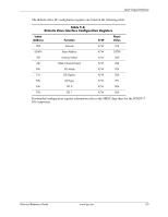
Input/Output Interfaces SATA Configuration Registers The SATA controller is configured as a PCI device with bus mastering capability. The PCI configuration registers for the SATA controller function (PCI device #31, function #2) are listed in Table 5-1. Table 5-1. SATA PCI Configuration Registers (82801, Device 31/Function 2) PCI Conf. Addr. Register Reset Value PCI Conf. Addr. Register Reset Value 00-01h Vender ID 8086h 0F..1Fh Reserved 0's 02-03h Device ID 24D1h 10-17h Pri. Cmd, Cntrl. Addrs. 1 (both) 04-05h PCI Command 0000h 18-1Fh Sec. Cmd, Cntrl. Addrs. 1 (both) 06-07h PCI Status 02B0h 20-23h BMstr Base Address 1 08h Revision ID 00h 2C, 2Dh Subsystem Vender ID 0000h 09h Programming 8Ah 2E, 2Fh Subsystem ID 0000h 0Ah Sub-Class 01h 34h Capabilities pointer 80h 0Bh Base Class Code 01h 3Ch Interrupt Line 00h 0Dh Master Latency Timer 00h 3Dh Interrupt Pin 01h 0Eh Header Type 00h 40-57h Timing, Control All 0's SATA Bus Master Control Registers The SATA interface can perform PCI bus master operations using the registers listed in Table 5-2. These registers occupy 16 bytes of variable I/O space set by software and indicated by PCI configuration register 20h in the previous table. As indicated, these registers are virtually a copy of those used by EIDE operations discussed in the EIDE section. I/O Addr. Offset 00h 02h 04h 08h 0Ah 0Ch Table 5-2. IDE Bus Master Control Registers Size (Bytes) Register 1 Bus Master IDE Command (Primary) 1 Bus Master IDE Status (Primary) 4 Bus Master IDE Descriptor Pointer (Primary) 1 Bus Master IDE Command (Secondary) 2 Bus Master IDE Status (Secondary) 4 Bus Master IDE Descriptor Pointer (Secondary Default Value 00h 00h 0000 0000h 00h 00h 0000 0000h 5-2 www.hp.com Technical Reference Guide
-
 1
1 -
2
-
3
-
4
-
5
-
6
-
7
-
8
-
9
-
10
-
11
-
12
-
13
-
14
-
15
-
16
-
17
-
18
-
19
-
20
-
21
-
22
-
23
-
24
-
25
-
26
-
27
-
28
-
29
-
30
-
31
-
32
-
33
-
34
-
35
-
36
-
37
-
38
-
39
-
40
-
41
-
42
-
43
-
44
-
45
-
46
-
47
-
48
-
49
-
50
-
51
-
52
-
53
-
54
-
55
-
56
-
57
-
58
-
59
-
60
-
61
-
62
-
63
-
64
-
65
-
66
-
67
-
68
-
69
-
70
-
71
-
72
-
73
-
74
-
 75
75 -
 76
76 -
 77
77 -
 78
78 -
 79
79 -
 80
80 -
 81
81 -
 82
82 -
 83
83 -
 84
84 -
 85
85 -
86
-
87
-
88
-
89
-
90
-
91
-
92
-
93
-
94
-
95
-
96
-
97
-
98
-
99
-
100
-
101
-
102
-
103
-
104
-
105
-
106
-
107
-
108
-
109
-
110
-
111
-
112
-
113
-
114
-
115
-
116
-
117
-
118
-
119
-
120
-
121
-
122
-
123
-
124
-
125
-
126
-
127
-
128
-
129
-
130
-
131
-
132
-
133
-
134
-
135
-
136
-
137
-
138
-
139
-
140
-
141
-
142
-
143
-
144
-
145
-
146
-
147
-
148
-
149
-
150
-
151
-
152
-
153
-
154
-
155
-
156
-
157
-
158
-
159
-
160
-
161
-
162
-
163
-
164
-
165
-
166
-
167
-
168
-
169
-
170
-
171
-
172
-
173
-
174
-
175
-
176
-
177
-
178
-
179
-
180
-
181
-
182
-
183
-
184
-
185
-
186
-
187
-
188
-
189
-
190
-
191
-
192
-
193
-
194
-
195
-
196
 |
 |