HP Dc7700 HP Compaq dx7300 and dc7700 Business PC Technical Reference Guide, 1 - Page 78
Write 07h to I/O register 2Eh.
 |
UPC - 882780715318
View all HP Dc7700 manuals
Add to My Manuals
Save this manual to your list of manuals |
Page 78 highlights
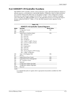
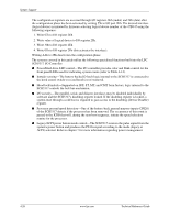
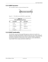
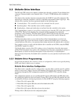
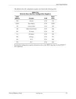
System Support The configuration registers are accessed through I/O registers 2Eh (index) and 2Fh (data) after the configuration phase has been activated by writing 55h to I/O port 2Eh. The desired interface (logical device) is initiated by firmware selecting logical device number of the 47B347 using the following sequence: 1. Write 07h to I/O register 2Eh. 2. Write value of logical device to I/O register 2Fh. 3. Write 30h to I/O register 2Eh. 4. Write 01h to I/O register 2Fh (this activates the interface). Writing AAh to 2Eh deactivates the configuration phase. The systems covered in this guide utilize the following specialized functions built into the LPC SCH5317 I/O Controller: ■ Power/Hard drive LED control-The I/O controller provides color and blink control for the front panel LEDs used for indicating system events (refer to Table 4-14). ■ Intruder sensing-The battery-backed D-latch logic internal to the SCH5317 is connected to the hood sensor switch to record hood (cover) removal. ■ Hood lock/unlock-Supported on SFF, ST, MT, and CMT form factors, logic internal to the SCH5317 controls the lock bar mechanism. ■ I/O security-The parallel, serial, and diskette interfaces may be disabled individually by software and the SCH5317's disabling register locked. If the disabling register is locked, a system reset through a cold boot is required to gain access to the disabling (Device Disable) register. ■ Processor present/speed detection-One of the battery-back general-purpose inputs (GPI26) of the SCH5317 detects if the processor has been removed. The occurrence of this event is passed to the ICH8 that will, during the next boot sequence, initiate the speed selection routine for the processor. ■ Legacy/ACPI power button mode control-The SCH5317 receives the pulse signal from the system's power button and produces the PS On signal according to the mode (legacy or ACPI) selected. Refer to chapter 7 for more information regarding power management. 4-26 www.hp.com Technical Reference Guide
-
 1
1 -
2
-
3
-
4
-
5
-
6
-
7
-
8
-
9
-
10
-
11
-
12
-
13
-
14
-
15
-
16
-
17
-
18
-
19
-
20
-
21
-
22
-
23
-
24
-
25
-
26
-
27
-
28
-
29
-
30
-
31
-
32
-
33
-
34
-
35
-
36
-
37
-
38
-
39
-
40
-
41
-
42
-
43
-
44
-
45
-
46
-
47
-
48
-
49
-
50
-
51
-
52
-
53
-
54
-
55
-
56
-
57
-
58
-
59
-
60
-
61
-
62
-
63
-
64
-
65
-
66
-
67
-
68
-
69
-
70
-
71
-
72
-
 73
73 -
 74
74 -
 75
75 -
 76
76 -
 77
77 -
 78
78 -
 79
79 -
 80
80 -
 81
81 -
 82
82 -
 83
83 -
84
-
85
-
86
-
87
-
88
-
89
-
90
-
91
-
92
-
93
-
94
-
95
-
96
-
97
-
98
-
99
-
100
-
101
-
102
-
103
-
104
-
105
-
106
-
107
-
108
-
109
-
110
-
111
-
112
-
113
-
114
-
115
-
116
-
117
-
118
-
119
-
120
-
121
-
122
-
123
-
124
-
125
-
126
-
127
-
128
-
129
-
130
-
131
-
132
-
133
-
134
-
135
-
136
-
137
-
138
-
139
-
140
-
141
-
142
-
143
-
144
-
145
-
146
-
147
-
148
-
149
-
150
-
151
-
152
-
153
-
154
-
155
-
156
-
157
-
158
-
159
-
160
-
161
-
162
-
163
-
164
-
165
-
166
-
167
-
168
-
169
-
170
-
171
-
172
-
173
-
174
-
175
-
176
-
177
-
178
-
179
-
180
-
181
-
182
-
183
-
184
-
185
-
186
-
187
-
188
-
189
-
190
-
191
-
192
-
193
-
194
-
195
-
196
 |
 |