HP Dc7700 HP Compaq dx7300 and dc7700 Business PC Technical Reference Guide, 1 - Page 95
Pointing Device Interface Operation, 5.6.3 Keyboard/Pointing Device Interface Programming
 |
UPC - 882780715318
View all HP Dc7700 manuals
Add to My Manuals
Save this manual to your list of manuals |
Page 95 highlights
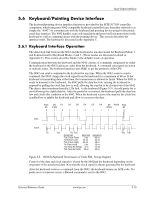
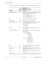
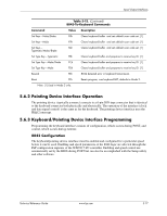
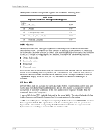
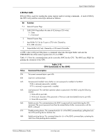
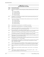
Input/Output Interfaces Table 5-13. (Continued) 8042-To-Keyboard Commands Command Value Description Set Keys-Make/Brake F8h Clears keyboard buffer and sets default scan code set. [1] Set Keys-Make F9h Clears keyboard buffer and sets default scan code set. [1] Set Keys- Typematic/Make/Brake FAh Clears keyboard buffer and sets default scan code set. [1] Set Type Key-Typematic FBh Clears keyboard buffer and prepares to receive key ID. [1] Set Type Key-Make/Brake FCh Clears keyboard buffer and prepares to receive key ID. [1] Set Type Key-Make FDh Clears keyboard buffer and prepares to receive key ID. [1] Resend FEh 8042 detected error in keyboard transmission. Reset FFh Resets program, runs keyboard BAT, defaults to Mode 2. Note: [1] Used in Mode 3 only. 5.6.2 Pointing Device Interface Operation The pointing device (typically a mouse) connects to a 6-pin DIN-type connector that is identical to the keyboard connector both physically and electrically. The operation of the interface (clock and data signal control) is the same as for the keyboard. The pointing device interface uses the IRQ12 interrupt. 5.6.3 Keyboard/Pointing Device Interface Programming Programming the keyboard interface consists of configuration, which occurs during POST, and control, which occurs during runtime. 8042 Configuration The keyboard/pointing device interface must be enabled and configured for a particular speed before it can be used. Enabling and speed parameters of the 8042 logic are affected through the PnP configuration registers of the SCH5317 I/O controller. Enabling and speed control are automatically set by the BIOS during POST but can also be accomplished with the Setup utility and other software. Technical Reference Guide www.hp.com 5-17
-
 1
1 -
2
-
3
-
4
-
5
-
6
-
7
-
8
-
9
-
10
-
11
-
12
-
13
-
14
-
15
-
16
-
17
-
18
-
19
-
20
-
21
-
22
-
23
-
24
-
25
-
26
-
27
-
28
-
29
-
30
-
31
-
32
-
33
-
34
-
35
-
36
-
37
-
38
-
39
-
40
-
41
-
42
-
43
-
44
-
45
-
46
-
47
-
48
-
49
-
50
-
51
-
52
-
53
-
54
-
55
-
56
-
57
-
58
-
59
-
60
-
61
-
62
-
63
-
64
-
65
-
66
-
67
-
68
-
69
-
70
-
71
-
72
-
73
-
74
-
75
-
76
-
77
-
78
-
79
-
80
-
81
-
82
-
83
-
84
-
85
-
86
-
87
-
88
-
89
-
 90
90 -
 91
91 -
 92
92 -
 93
93 -
 94
94 -
 95
95 -
 96
96 -
 97
97 -
 98
98 -
 99
99 -
 100
100 -
101
-
102
-
103
-
104
-
105
-
106
-
107
-
108
-
109
-
110
-
111
-
112
-
113
-
114
-
115
-
116
-
117
-
118
-
119
-
120
-
121
-
122
-
123
-
124
-
125
-
126
-
127
-
128
-
129
-
130
-
131
-
132
-
133
-
134
-
135
-
136
-
137
-
138
-
139
-
140
-
141
-
142
-
143
-
144
-
145
-
146
-
147
-
148
-
149
-
150
-
151
-
152
-
153
-
154
-
155
-
156
-
157
-
158
-
159
-
160
-
161
-
162
-
163
-
164
-
165
-
166
-
167
-
168
-
169
-
170
-
171
-
172
-
173
-
174
-
175
-
176
-
177
-
178
-
179
-
180
-
181
-
182
-
183
-
184
-
185
-
186
-
187
-
188
-
189
-
190
-
191
-
192
-
193
-
194
-
195
-
196
 |
 |