HP Dc7700 HP Compaq dx7300 and dc7700 Business PC Technical Reference Guide, 1 - Page 120
VGA Monitor Connector, Table 6-1., DB-15 Monitor Connector Pinout
 |
UPC - 882780715318
View all HP Dc7700 manuals
Add to My Manuals
Save this manual to your list of manuals |
Page 120 highlights
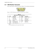
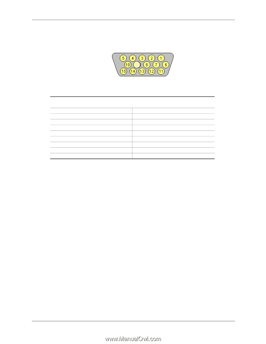
Integrated Graphics Subsystem 6.5 VGA Monitor Connector These systems includes a standard VGA connector (Figure 6-3) for attaching an analog monitor: 9 Figure 6 3. DB-15 VGA Monitor Connector, (as viewed from rear of chassis). Pin Signal 1R 2G 3B 4 NC 5 GND 6 R GND 7 G GND 8 B GND Table 6-1. DB-15 Monitor Connector Pinout Description Pin Signal Description Red Analog 9 PWR +5 VDC (fused) [1] Blue Analog 10 GND Ground Green Analog 11 NC Not Connected Not Connected 12 SDA DDC2-B Data Ground 13 HSync Horizontal Sync Red Analog Ground 14 VSync Vertical Sync Blue Analog Ground 15 SCL DDC2-B Clock Green Analog Ground -- -- -- NOTES: [1] Fuse automatically resets when excessive load is removed. 6-6 www.hp.com Technical Reference Guide
-
 1
1 -
2
-
3
-
4
-
5
-
6
-
7
-
8
-
9
-
10
-
11
-
12
-
13
-
14
-
15
-
16
-
17
-
18
-
19
-
20
-
21
-
22
-
23
-
24
-
25
-
26
-
27
-
28
-
29
-
30
-
31
-
32
-
33
-
34
-
35
-
36
-
37
-
38
-
39
-
40
-
41
-
42
-
43
-
44
-
45
-
46
-
47
-
48
-
49
-
50
-
51
-
52
-
53
-
54
-
55
-
56
-
57
-
58
-
59
-
60
-
61
-
62
-
63
-
64
-
65
-
66
-
67
-
68
-
69
-
70
-
71
-
72
-
73
-
74
-
75
-
76
-
77
-
78
-
79
-
80
-
81
-
82
-
83
-
84
-
85
-
86
-
87
-
88
-
89
-
90
-
91
-
92
-
93
-
94
-
95
-
96
-
97
-
98
-
99
-
100
-
101
-
102
-
103
-
104
-
105
-
106
-
107
-
108
-
109
-
110
-
111
-
112
-
113
-
114
-
 115
115 -
 116
116 -
 117
117 -
 118
118 -
 119
119 -
 120
120 -
 121
121 -
 122
122 -
 123
123 -
 124
124 -
 125
125 -
126
-
127
-
128
-
129
-
130
-
131
-
132
-
133
-
134
-
135
-
136
-
137
-
138
-
139
-
140
-
141
-
142
-
143
-
144
-
145
-
146
-
147
-
148
-
149
-
150
-
151
-
152
-
153
-
154
-
155
-
156
-
157
-
158
-
159
-
160
-
161
-
162
-
163
-
164
-
165
-
166
-
167
-
168
-
169
-
170
-
171
-
172
-
173
-
174
-
175
-
176
-
177
-
178
-
179
-
180
-
181
-
182
-
183
-
184
-
185
-
186
-
187
-
188
-
189
-
190
-
191
-
192
-
193
-
194
-
195
-
196
 |
 |
6-6
www.hp.com
Technical Reference Guide
Integrated Graphics Subsystem
6.5 VGA Monitor Connector
These systems includes a standard VGA connector (Figure 6-3) for attaching an analog monitor:
Figure 6 3. DB-15 VGA Monitor Connector, (as viewed from rear of chassis).
NOTES:
[1] Fuse automatically resets when excessive load is removed.
Table 6-1.
DB-15 Monitor Connector Pinout
Pin
Signal
Description
Pin
Signal
Description
1
R
Red Analog
9
PWR
+5 VDC (fused) [1]
2
G
Blue Analog
10
GND
Ground
3
B
Green Analog
11
NC
Not Connected
4
NC
Not Connected
12
SDA
DDC2-B Data
5
GND
Ground
13
HSync
Horizontal Sync
6
R GND
Red Analog Ground
14
VSync
Vertical Sync
7
G GND
Blue Analog Ground
15
SCL
DDC2-B Clock
8
B GND
Green Analog Ground
--
--
--
9