HP Dc7700 HP Compaq dx7300 and dc7700 Business PC Technical Reference Guide, 1 - Page 93
Keyboard/Pointing Device Interface, 5.6.1 Keyboard Interface Operation
 |
UPC - 882780715318
View all HP Dc7700 manuals
Add to My Manuals
Save this manual to your list of manuals |
Page 93 highlights
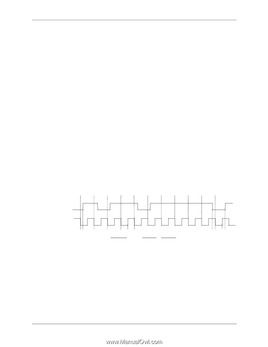
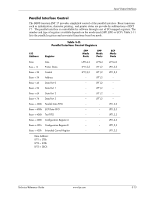
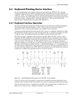
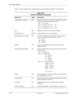
Input/Output Interfaces 5.6 Keyboard/Pointing Device Interface The keyboard/pointing device interface function is provided by the SCH5317 I/O controller component, which integrates 8042-compatible keyboard controller logic (hereafter referred to as simply the "8042") to communicate with the keyboard and pointing device using bi-directional serial data transfers. The 8042 handles scan code translation and password lock protection for the keyboard as well as communications with the pointing device. This section describes the interface itself. The keyboard is discussed in the Appendix C. 5.6.1 Keyboard Interface Operation The data/clock link between the 8042 and the keyboard is uni-directional for Keyboard Mode 1 and bi-directional for Keyboard Modes 2 and 3. (These modes are discussed in detail in Appendix C). This section describes Mode 2 (the default) mode of operation. Communication between the keyboard and the 8042 consists of commands (originated by either the keyboard or the 8042) and scan codes from the keyboard. A command can request an action or indicate status. The keyboard interface uses IRQ1 to get the attention of the CPU. The 8042 can send a command to the keyboard at any time. When the 8042 wants to send a command, the 8042 clamps the clock signal from the keyboard for a minimum of 60 us. If the keyboard is transmitting data at that time, the transmission is allowed to finish. When the 8042 is ready to transmit to the keyboard, the 8042 pulls the data line low, causing the keyboard to respond by pulling the clock line low as well, allowing the start bit to be clocked out of the 8042. The data is then transferred serially, LSb first, to the keyboard (Figure 5-5). An odd parity bit is sent following the eighth data bit. After the parity bit is received, the keyboard pulls the data line low and clocks this condition to the 8042. When the keyboard receives the stop bit, the clock line is pulled low to inhibit the keyboard and allow it to process the data. Start D0 D1 D2 D3 D4 D5 D6 D7 Parity Stop Bit (LSb) (MSb) Bit 0 1 0 1 1 0 1 1 1 1 0 Data Clock Th Tcy Tcl Tch Parameter Minimum Maximum Tcy (Cycle Time) 0 us 80 us Tcl (Clock Low) 25 us 35 us Tch (Clock High) 25 us 45 us Th (Data Hold) 0 us 25 us Tss (Stop Bit Setup) 8 us 20 us Tsh (Stop Bit Hold) 15 us 25 us Tss Tsh Figure 5-5. 8042-To-Keyboard Transmission of Code EDh, Timing Diagram Control of the data and clock signals is shared by the 8042and the keyboard depending on the originator of the transferred data. Note that the clock signal is always generated by the keyboard. After the keyboard receives a command from the 8042, the keyboard returns an ACK code. If a parity error or timeout occurs, a Resend command is sent to the 8042. Technical Reference Guide www.hp.com 5-15
-
 1
1 -
2
-
3
-
4
-
5
-
6
-
7
-
8
-
9
-
10
-
11
-
12
-
13
-
14
-
15
-
16
-
17
-
18
-
19
-
20
-
21
-
22
-
23
-
24
-
25
-
26
-
27
-
28
-
29
-
30
-
31
-
32
-
33
-
34
-
35
-
36
-
37
-
38
-
39
-
40
-
41
-
42
-
43
-
44
-
45
-
46
-
47
-
48
-
49
-
50
-
51
-
52
-
53
-
54
-
55
-
56
-
57
-
58
-
59
-
60
-
61
-
62
-
63
-
64
-
65
-
66
-
67
-
68
-
69
-
70
-
71
-
72
-
73
-
74
-
75
-
76
-
77
-
78
-
79
-
80
-
81
-
82
-
83
-
84
-
85
-
86
-
87
-
 88
88 -
 89
89 -
 90
90 -
 91
91 -
 92
92 -
 93
93 -
 94
94 -
 95
95 -
 96
96 -
 97
97 -
 98
98 -
99
-
100
-
101
-
102
-
103
-
104
-
105
-
106
-
107
-
108
-
109
-
110
-
111
-
112
-
113
-
114
-
115
-
116
-
117
-
118
-
119
-
120
-
121
-
122
-
123
-
124
-
125
-
126
-
127
-
128
-
129
-
130
-
131
-
132
-
133
-
134
-
135
-
136
-
137
-
138
-
139
-
140
-
141
-
142
-
143
-
144
-
145
-
146
-
147
-
148
-
149
-
150
-
151
-
152
-
153
-
154
-
155
-
156
-
157
-
158
-
159
-
160
-
161
-
162
-
163
-
164
-
165
-
166
-
167
-
168
-
169
-
170
-
171
-
172
-
173
-
174
-
175
-
176
-
177
-
178
-
179
-
180
-
181
-
182
-
183
-
184
-
185
-
186
-
187
-
188
-
189
-
190
-
191
-
192
-
193
-
194
-
195
-
196
 |
 |