HP LaserJet 3200 Service Manual - Page 121
Fusing element, The fusing element is held in place on each end by two metal spring
 |
View all HP LaserJet 3200 manuals
Add to My Manuals
Save this manual to your list of manuals |
Page 121 highlights
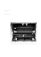
Note Fusing element 1 Remove the DIMMs, the back, right, and left covers, the internal paper guide, and the top cover (see pages 89 through 95). 2 Also remove the output roller and the delivery assembly (see pages 114 through 117). Pay special attention to the way these metal clips are attached to the printer chassis before you remove them. This will make reassembly easier. The fusing element is held in place on each end by two metal springloaded clips. Each clip has a small white lever next to it. These levers must be in the "up" position. 3 Push each clip down and back, releasing it from the printer chassis. Figure 47. Fusing element removal (1 of 4) EN Internal assemblies 119
-
 1
1 -
2
-
3
-
4
-
5
-
6
-
7
-
8
-
9
-
10
-
11
-
12
-
13
-
14
-
15
-
16
-
17
-
18
-
19
-
20
-
21
-
22
-
23
-
24
-
25
-
26
-
27
-
28
-
29
-
30
-
31
-
32
-
33
-
34
-
35
-
36
-
37
-
38
-
39
-
40
-
41
-
42
-
43
-
44
-
45
-
46
-
47
-
48
-
49
-
50
-
51
-
52
-
53
-
54
-
55
-
56
-
57
-
58
-
59
-
60
-
61
-
62
-
63
-
64
-
65
-
66
-
67
-
68
-
69
-
70
-
71
-
72
-
73
-
74
-
75
-
76
-
77
-
78
-
79
-
80
-
81
-
82
-
83
-
84
-
85
-
86
-
87
-
88
-
89
-
90
-
91
-
92
-
93
-
94
-
95
-
96
-
97
-
98
-
99
-
100
-
101
-
102
-
103
-
104
-
105
-
106
-
107
-
108
-
109
-
110
-
111
-
112
-
113
-
114
-
115
-
 116
116 -
 117
117 -
 118
118 -
 119
119 -
 120
120 -
 121
121 -
 122
122 -
 123
123 -
 124
124 -
 125
125 -
 126
126 -
127
-
128
-
129
-
130
-
131
-
132
-
133
-
134
-
135
-
136
-
137
-
138
-
139
-
140
-
141
-
142
-
143
-
144
-
145
-
146
-
147
-
148
-
149
-
150
-
151
-
152
-
153
-
154
-
155
-
156
-
157
-
158
-
159
-
160
-
161
-
162
-
163
-
164
-
165
-
166
-
167
-
168
-
169
-
170
-
171
-
172
-
173
-
174
-
175
-
176
-
177
-
178
-
179
-
180
-
181
-
182
-
183
-
184
-
185
-
186
-
187
-
188
-
189
-
190
-
191
-
192
-
193
-
194
-
195
-
196
-
197
-
198
-
199
-
200
-
201
-
202
-
203
-
204
-
205
-
206
-
207
-
208
-
209
-
210
-
211
-
212
-
213
-
214
-
215
-
216
-
217
-
218
-
219
-
220
-
221
-
222
-
223
-
224
-
225
-
226
-
227
-
228
-
229
-
230
-
231
-
232
-
233
-
234
-
235
-
236
-
237
-
238
-
239
-
240
-
241
-
242
-
243
-
244
-
245
-
246
-
247
-
248
-
249
-
250
-
251
-
252
-
253
-
254
-
255
-
256
-
257
-
258
-
259
-
260
-
261
-
262
-
263
-
264
-
265
-
266
-
267
-
268
 |
 |

EN
Internal assemblies
119
Fusing element
1
Remove the DIMMs, the back, right, and left covers, the internal
paper guide, and the top cover (see pages 89 through 95).
2
Also remove the output roller and the delivery assembly (see
pages 114 through 117).
Note
Pay special attention to the way these metal clips are attached to the
printer chassis before you remove them. This will make reassembly
easier.
The fusing element is held in place on each end by two metal spring-
loaded clips. Each clip has a small white lever next to it. These levers
must be in the “up” position.
3
Push each clip down and back, releasing it from the printer
chassis.
Figure 47.
Fusing element removal (1 of 4)