HP Surestore Disk Array FC60 HP SureStore E Disk Array 12H User's and Service - Page 241
Install replacement 19 PDUs, Remove existing 56 PDUs
 |
View all HP Surestore Disk Array FC60 manuals
Add to My Manuals
Save this manual to your list of manuals |
Page 241 highlights
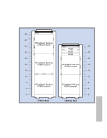
Appendix D. Back-to-Back Racking Installation Brief Summary of Installation Steps The sequence below describes the general approach for installing the field upgrade for back-to-back racking. These steps may vary slightly, depending on the particular installation. The installation process is described in more detail in the following, "Installation Procedure" section. 1. Confirm power requirements 2. Take disk arrays offline and power down rack 3. Disconnect all power to the rack 4. Remove the rack top, sides, and back door and door hinges and latch catch (the door will not be re-installed and can be set aside) 5. Remove existing 56" PDUs 6. If necessary, remove array enclosures (array enclosures may need to be removed to be repositioned, see step 4, below) 7. Install the exhaust fan assembly 8. Install rail kits as needed 9. Install replacement 19" PDU angle brackets 10. Install/re-install disk enclosures 11. Install replacement 19" PDUs 12. Install the power cables 13. Install the SCSI cables 14. Complete the installation Some of the installation procedures identify the installation of kits. The detailed installation procedures for these kits are included in documentation supplied with the kit (such as, the exhaust fan assembly kit, rail kit, and power (PDU) upgrade kit). 241 Racking
-
 1
1 -
2
-
3
-
4
-
5
-
6
-
7
-
8
-
9
-
10
-
11
-
12
-
13
-
14
-
15
-
16
-
17
-
18
-
19
-
20
-
21
-
22
-
23
-
24
-
25
-
26
-
27
-
28
-
29
-
30
-
31
-
32
-
33
-
34
-
35
-
36
-
37
-
38
-
39
-
40
-
41
-
42
-
43
-
44
-
45
-
46
-
47
-
48
-
49
-
50
-
51
-
52
-
53
-
54
-
55
-
56
-
57
-
58
-
59
-
60
-
61
-
62
-
63
-
64
-
65
-
66
-
67
-
68
-
69
-
70
-
71
-
72
-
73
-
74
-
75
-
76
-
77
-
78
-
79
-
80
-
81
-
82
-
83
-
84
-
85
-
86
-
87
-
88
-
89
-
90
-
91
-
92
-
93
-
94
-
95
-
96
-
97
-
98
-
99
-
100
-
101
-
102
-
103
-
104
-
105
-
106
-
107
-
108
-
109
-
110
-
111
-
112
-
113
-
114
-
115
-
116
-
117
-
118
-
119
-
120
-
121
-
122
-
123
-
124
-
125
-
126
-
127
-
128
-
129
-
130
-
131
-
132
-
133
-
134
-
135
-
136
-
137
-
138
-
139
-
140
-
141
-
142
-
143
-
144
-
145
-
146
-
147
-
148
-
149
-
150
-
151
-
152
-
153
-
154
-
155
-
156
-
157
-
158
-
159
-
160
-
161
-
162
-
163
-
164
-
165
-
166
-
167
-
168
-
169
-
170
-
171
-
172
-
173
-
174
-
175
-
176
-
177
-
178
-
179
-
180
-
181
-
182
-
183
-
184
-
185
-
186
-
187
-
188
-
189
-
190
-
191
-
192
-
193
-
194
-
195
-
196
-
197
-
198
-
199
-
200
-
201
-
202
-
203
-
204
-
205
-
206
-
207
-
208
-
209
-
210
-
211
-
212
-
213
-
214
-
215
-
216
-
217
-
218
-
219
-
220
-
221
-
222
-
223
-
224
-
225
-
226
-
227
-
228
-
229
-
230
-
231
-
232
-
233
-
234
-
235
-
 236
236 -
 237
237 -
 238
238 -
 239
239 -
 240
240 -
 241
241 -
 242
242 -
 243
243 -
 244
244 -
 245
245 -
 246
246 -
247
-
248
-
249
-
250
-
251
-
252
-
253
-
254
-
255
-
256
-
257
-
258
-
259
-
260
-
261
-
262
-
263
-
264
-
265
-
266
-
267
-
268
-
269
-
270
-
271
-
272
-
273
-
274
-
275
-
276
 |
 |
