HP Surestore Disk Array FC60 HP SureStore E Disk Array 12H User's and Service - Page 248
Upgrade Kit Quick Installation Guide., Install Replacement PDUs, Install the power cables
 |
View all HP Surestore Disk Array FC60 manuals
Add to My Manuals
Save this manual to your list of manuals |
Page 248 highlights
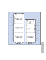
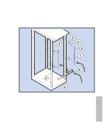
Appendix D. Back-to-Back Racking Installation Procedure 7. Install Replacement PDUs a) Attach two PDUs vertically to the brackets installed in the previous step. Position the PDU with its large power receptacle toward the bottom and install as described in the A4915A Power Upgrade Kit Quick Installation Guide. b) Install the horizontal PDU with the large power receptacle to the right (facing the rear of the rack). Install the PDU in the holes indicated below, for the specific cabinet, as described in the power upgrade kit quick installation guide: Rack 1.6 Meter Rack 2-meter Rack - EIA Holes (as counted from the bottom of the rack 89 (middle hole of EIA unit 30) 41 (middle hole of EIA unit 14) 8. Install the power cables Connect each power cable from an array power supply (P1, P2, and P3) to a different PDU (PDU #1, PDU#2, and PDU #3) as shown in Figure 52 Power Cable Schematic. To help ensure that individual array supplies get power from a different PDU, divide the cabinet into vertical thirds, looking from the back. All power supplies on the right side go to PDU#1 mounted on the upper right side; all power supplies in the middle of the arrays go to PDU #2 the horizontal PDU; and, all power supplies to the left go to PDU #3 on the upper left side. Figure 52 illustrates the cabling for a 2-meter rack with 6 units. However, this diagram applies to any configuration, a 2-meter with 5 units or 1.6 meter with 3 or 4 units. Simply follow the cabling for the number of arrays you have installed. Route the cables from the back of the disk array, out and around the outside of the rack column, and into the PDU as shown in Figure 53. Do not connect more than 8 power cables into one PDU. Racking 248
-
 1
1 -
2
-
3
-
4
-
5
-
6
-
7
-
8
-
9
-
10
-
11
-
12
-
13
-
14
-
15
-
16
-
17
-
18
-
19
-
20
-
21
-
22
-
23
-
24
-
25
-
26
-
27
-
28
-
29
-
30
-
31
-
32
-
33
-
34
-
35
-
36
-
37
-
38
-
39
-
40
-
41
-
42
-
43
-
44
-
45
-
46
-
47
-
48
-
49
-
50
-
51
-
52
-
53
-
54
-
55
-
56
-
57
-
58
-
59
-
60
-
61
-
62
-
63
-
64
-
65
-
66
-
67
-
68
-
69
-
70
-
71
-
72
-
73
-
74
-
75
-
76
-
77
-
78
-
79
-
80
-
81
-
82
-
83
-
84
-
85
-
86
-
87
-
88
-
89
-
90
-
91
-
92
-
93
-
94
-
95
-
96
-
97
-
98
-
99
-
100
-
101
-
102
-
103
-
104
-
105
-
106
-
107
-
108
-
109
-
110
-
111
-
112
-
113
-
114
-
115
-
116
-
117
-
118
-
119
-
120
-
121
-
122
-
123
-
124
-
125
-
126
-
127
-
128
-
129
-
130
-
131
-
132
-
133
-
134
-
135
-
136
-
137
-
138
-
139
-
140
-
141
-
142
-
143
-
144
-
145
-
146
-
147
-
148
-
149
-
150
-
151
-
152
-
153
-
154
-
155
-
156
-
157
-
158
-
159
-
160
-
161
-
162
-
163
-
164
-
165
-
166
-
167
-
168
-
169
-
170
-
171
-
172
-
173
-
174
-
175
-
176
-
177
-
178
-
179
-
180
-
181
-
182
-
183
-
184
-
185
-
186
-
187
-
188
-
189
-
190
-
191
-
192
-
193
-
194
-
195
-
196
-
197
-
198
-
199
-
200
-
201
-
202
-
203
-
204
-
205
-
206
-
207
-
208
-
209
-
210
-
211
-
212
-
213
-
214
-
215
-
216
-
217
-
218
-
219
-
220
-
221
-
222
-
223
-
224
-
225
-
226
-
227
-
228
-
229
-
230
-
231
-
232
-
233
-
234
-
235
-
236
-
237
-
238
-
239
-
240
-
241
-
242
-
 243
243 -
 244
244 -
 245
245 -
 246
246 -
 247
247 -
 248
248 -
 249
249 -
 250
250 -
 251
251 -
 252
252 -
 253
253 -
254
-
255
-
256
-
257
-
258
-
259
-
260
-
261
-
262
-
263
-
264
-
265
-
266
-
267
-
268
-
269
-
270
-
271
-
272
-
273
-
274
-
275
-
276
 |
 |
