Intel 640 User Guide - Page 16
Processor Thermal/Mechanical Information, Thermal/Mechanical Design Guide
 |
UPC - 683728178901
View all Intel 640 manuals
Add to My Manuals
Save this manual to your list of manuals |
Page 16 highlights
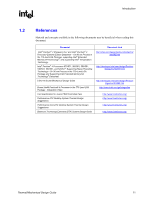
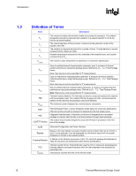
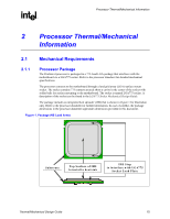
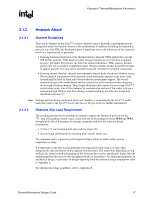
Processor Thermal/Mechanical Information R The primary function of the IHS is to transfer the non-uniform heat distribution from the die to the top of the IHS, out of which the heat flux is more uniform and spread over a larger surface area (not the entire IHS area). This allows more efficient heat transfer out of the package to an attached cooling device. The top surface of the IHS is designed to be the interface to the heatsink. The IHS also features a step that interfaces with the LGA775 socket load plate, as described in LGA775 Socket Mechanical Design Guide. The load from the load plate is distributed across two sides of the package onto a step on each side of the IHS. It is then distributed by the package across all of the contacts. When correctly actuated, the top surface of the IHS is above the load plate allowing proper installation of a heatsink on the top surface of the IHS. After actuation of the socket load plate, the seating plane of the package is flush with the seating plane of the socket. Package movement during socket actuation is along the Z direction (perpendicular to substrate) only. Refer to the LGA775 Socket Mechanical Design Guide for further information about the LGA775 socket. The datasheet gives details on the IHS geometry and tolerances, and material. The processor package has mechanical load limits that are specified in the processor datasheet. The specified maximum static and dynamic load limits should not be exceeded during their respective stress conditions. These include heatsink installation, removal, mechanical stress testing, and standard shipping conditions. • When a compressive static load is necessary to ensure thermal performance of the thermal interface material between the heatsink base and the IHS, it should not exceed the corresponding specification given in the processor datasheet. • When a compressive static load is necessary to ensure mechanical performance, it should remain in the minimum/maximum range specified in the processor datasheet • The heatsink mass can also generate additional dynamic compressive load to the package during a mechanical shock event. Amplification factors due to the impact force during shock must be taken into account in dynamic load calculations. The total combination of dynamic and static compressive load should not exceed the processor datasheet compressive dynamic load specification during a vertical shock. For example, with a 0.454 kg [1 lb] heatsink, an acceleration of 50G during an 11 ms trapezoidal shock with an amplification factor of 2 results in approximately a 445 N [100 lbf] dynamic load on the processor package. If a 178 N [40 lbf] static load is also applied on the heatsink for thermal performance of the thermal interface material the processor package could see up to a 623 N [140 lbf]. The calculation for the thermal solution of interest should be compared to the processor datasheet specification. No portion of the substrate should be used as a load-bearing surface. Finally, the datasheet provides package handling guidelines in terms of maximum recommended shear, tensile and torque loads for the processor IHS relative to a fixed substrate. These recommendations should be followed in particular for heatsink removal operations. 16 Thermal/Mechanical Design Guide
-
 1
1 -
2
-
3
-
4
-
5
-
6
-
7
-
8
-
9
-
10
-
 11
11 -
 12
12 -
 13
13 -
 14
14 -
 15
15 -
 16
16 -
 17
17 -
 18
18 -
 19
19 -
 20
20 -
 21
21 -
22
-
23
-
24
-
25
-
26
-
27
-
28
-
29
-
30
-
31
-
32
-
33
-
34
-
35
-
36
-
37
-
38
-
39
-
40
-
41
-
42
-
43
-
44
-
45
-
46
-
47
-
48
-
49
-
50
-
51
-
52
-
53
-
54
-
55
-
56
-
57
-
58
-
59
-
60
-
61
-
62
-
63
-
64
-
65
-
66
-
67
-
68
-
69
-
70
-
71
-
72
-
73
-
74
-
75
-
76
-
77
-
78
-
79
-
80
-
81
-
82
-
83
-
84
-
85
-
86
-
87
-
88
-
89
-
90
-
91
-
92
-
93
-
94
-
95
-
96
-
97
-
98
-
99
-
100
-
101
-
102
-
103
-
104
-
105
 |
 |