Intel 640 User Guide - Page 61
Appendix A LGA775 Socket Heatsink, Loading
 |
UPC - 683728178901
View all Intel 640 manuals
Add to My Manuals
Save this manual to your list of manuals |
Page 61 highlights
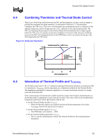
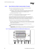
LGA775 Socket Heatsink Loading R Appendix A LGA775 Socket Heatsink Loading A.1 A.2 A.2.1 LGA775 Socket Heatsink Considerations Heatsink clip load is traditionally used for: • Mechanical performance in mechanical shock and vibration ⎯ Refer to Section 5.7.1 above for information on the structural design strategy for the Intel RCBFH-3 Reference Design • Thermal interface performance ⎯ Required preload depends on TIM ⎯ Preload can be low for thermal grease In addition to mechanical performance in shock and vibration and TIM performance, LGA775 socket requires a minimum heatsink preload to protect against fatigue failure of socket solder joints. Solder ball tensile stress is originally created when, after inserting a processor into the socket, the LGA775 socket load plate is actuated. In addition, solder joint shear stress is caused by coefficient of thermal expansion (CTE) mismatch induced shear loading. The solder joint compressive axial force (Faxial) induced by the heatsink preload helps to reduce the combined joint tensile and shear stress. Overall, the heatsink required preload is the minimum preload needed to meet all of the above requirements: Mechanical shock and vibration and TIM performance and LGA775 socket protection against fatigue failure. Metric for Heatsink Preload for ATX/µATX Designs Non-Compliant with Intel Reference Design Heatsink Preload Requirement Limitations Heatsink preload by itself is not an appropriate metric for solder joint force across various mechanical designs and does not take into account for example (not an exhaustive list): • Heatsink mounting hole span • Heatsink clip/fastener assembly stiffness and creep • Board stiffness and creep • Board stiffness is modified by fixtures like backing plate, chassis attach, etc. Thermal/Mechanical Design Guide 61
-
 1
1 -
2
-
3
-
4
-
5
-
6
-
7
-
8
-
9
-
10
-
11
-
12
-
13
-
14
-
15
-
16
-
17
-
18
-
19
-
20
-
21
-
22
-
23
-
24
-
25
-
26
-
27
-
28
-
29
-
30
-
31
-
32
-
33
-
34
-
35
-
36
-
37
-
38
-
39
-
40
-
41
-
42
-
43
-
44
-
45
-
46
-
47
-
48
-
49
-
50
-
51
-
52
-
53
-
54
-
55
-
 56
56 -
 57
57 -
 58
58 -
 59
59 -
 60
60 -
 61
61 -
 62
62 -
 63
63 -
 64
64 -
 65
65 -
 66
66 -
67
-
68
-
69
-
70
-
71
-
72
-
73
-
74
-
75
-
76
-
77
-
78
-
79
-
80
-
81
-
82
-
83
-
84
-
85
-
86
-
87
-
88
-
89
-
90
-
91
-
92
-
93
-
94
-
95
-
96
-
97
-
98
-
99
-
100
-
101
-
102
-
103
-
104
-
105
 |
 |